

Bolt官网:https://support.ludiq.io/(需要一定科学技术
前面是原文后边是翻译
求个关注,我会持续翻译的。
如果认为这篇文章帮到你了,请在评论区随便说点话,让我知道这个东西是有人看的。
Flow States & Super States
Before starting this section of the manual, we assume that you've read the Introduction, that you're familiar with the Basic Concepts and that you've created a State Machine. You should also have a good grip on how to use Flow Graphs, because they are found everywhere inside state graphs.
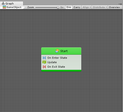
At this point, you should have a state graph with a single Start node.
States
States are self-contained behaviours that tell an object how it should behave when it's, well, in a particular state. They are often used for artificial intelligence (AI) behaviour or for object or scene structure.
For example, a state machine for an enemy NPC could have 4 states, "Patrolling", "Chasing", "Attacking" and "Fleeing", while a state machine for a door could have 3 states, "Locked", "Unlocked" and "Open".
In Bolt, there are two kinds of states.
Flow States: States that contain a nested flow graphs. This means you can use all the units and connections from the previous section in each state. Most of the states you will create will be flow states.
Super States: States that contain another nested state graph. They allow for the creation of hierarchical finite state machines (HSFM), that is, state machines within state machines. They are useful for advanced re-use and organization of your graphs.
Both types of states are "nesters", meaning that they work exactly like machines: their sub-graph can either be embedded, or referenced from a macro. Their inspector looks and behaves in the same way.
States are connected together with Transitions. We'll get to them in the next article. For now, let's focus on the state itself.
Creating States
To display the state creation menu, simply right-click anywhere in the empty grid. For now, simply choose Create Flow State.
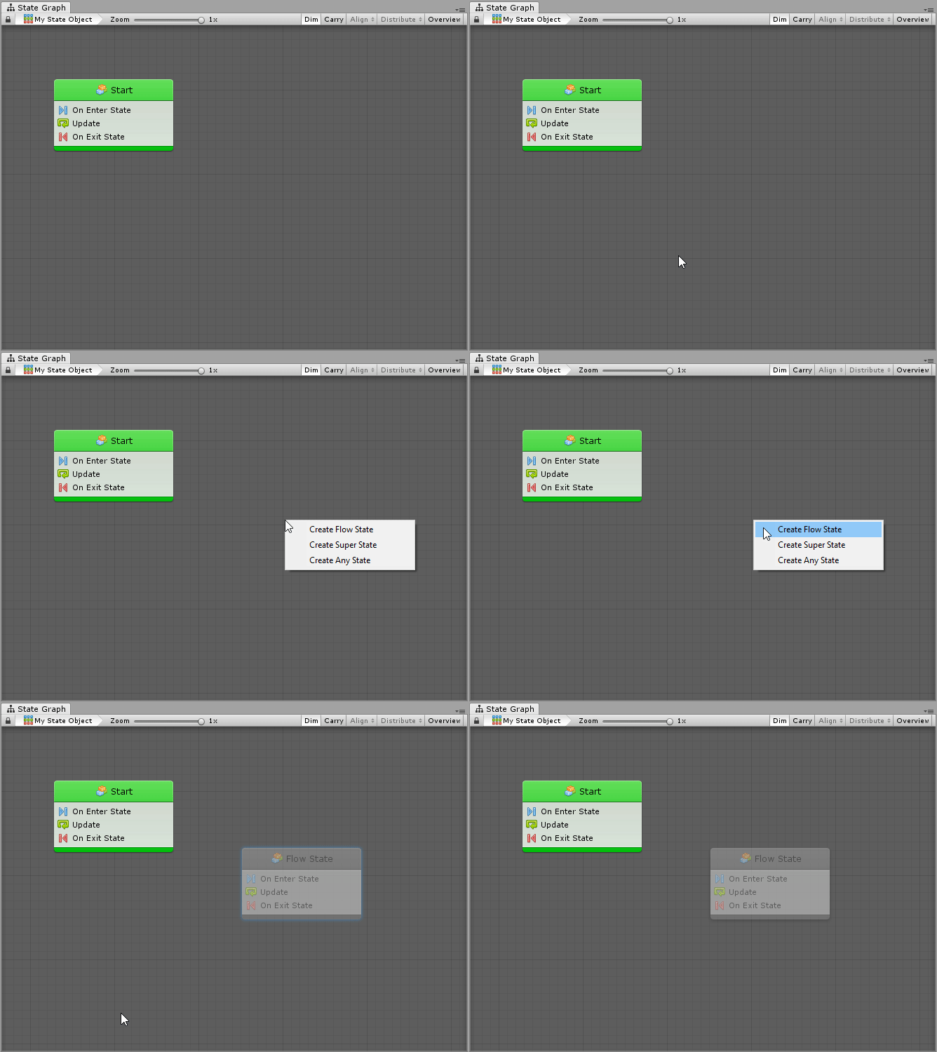
Just like units in flow graphs, the new state is dimmed because it is never entered. You can disable Dim in the toolbar if you don't want this behaviour.
Start State(s)
You can choose at which state the graph starts by choosing one or more Start State(s). To do so, just right click your state and choose Toggle Start. Start states are highlighted in green.
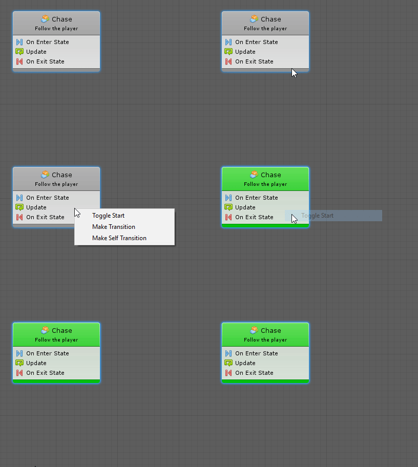
Unlike most finite state machine tools, Bolt allows for multiple start states. This means you can have parallel FSM's running in the same graph or even joining at some point. However, most often, you'll only need a single start state.
Any State
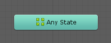
You can use the Any State to trigger transitions to other states, no matter which state is currently active. However, this state cannot receive any transition or execute any action.
Reading States
Let's take a look at the anatomy of a state.
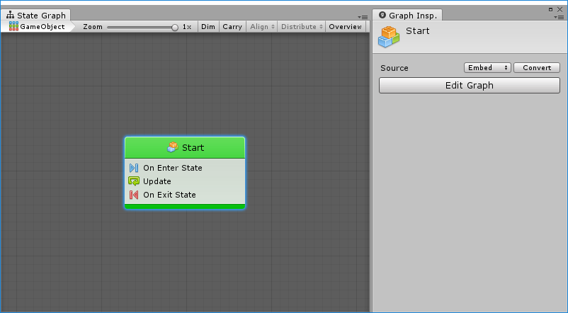
The top part of a state is its header. It displays the title and summary of its nested graph. These have no impact on functionality; they're simply a way for you to identify and comment your states. You can tell that it is a flow state by its little flow graph icon.
You'll notice that unlike units, states aren't much by themselves. Their inspector looks and works exactly like the one for machines. You can choose the source for the state's nested graph and open it by clicking the Edit Graph button. You can also double-click on the state node to open its nested graph.
Flow States
What you see as the body of a flow state is a list of all the events used in its nested flow graph. By default, new flow states are created with the On Enter State, Update and On Exit State events for convenience, but you can delete those if you don't need them and add any other event that you want.
Let's go ahead and double-click the state to open it.
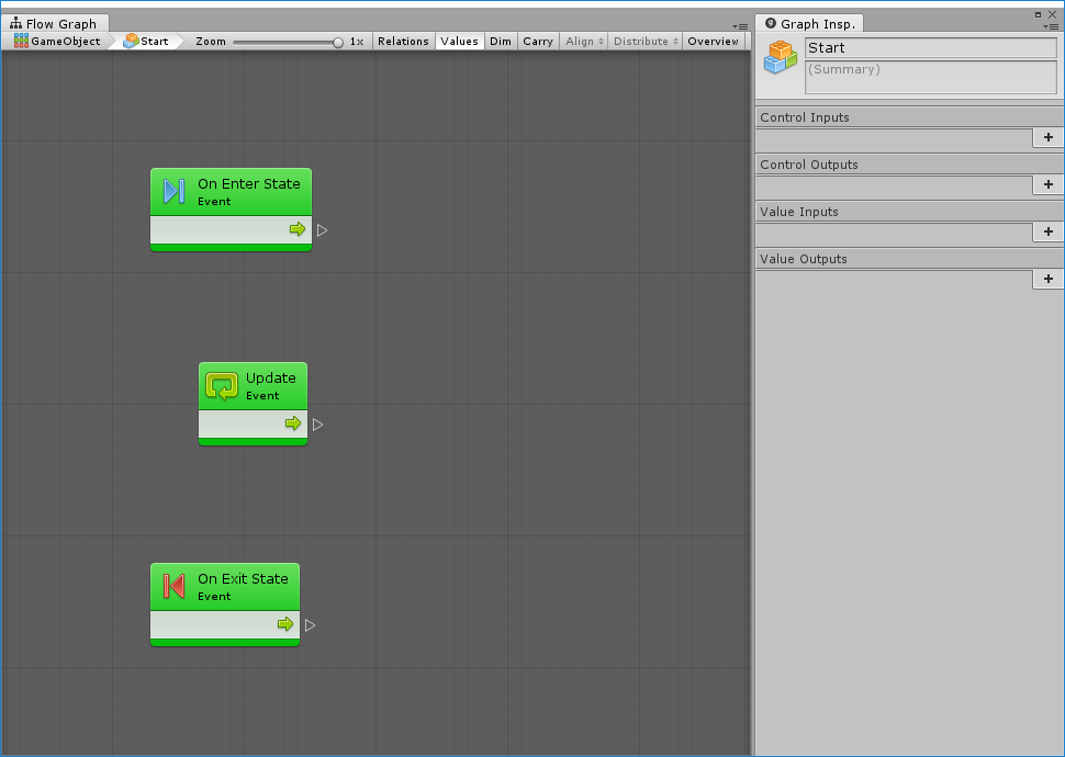
In the breadcrumbs at the top left, you can see that we are now within the state graph on our game object, inside the Startstate.

You can use this part of the toolbar to navigate back to parent graphs at any time.
At the top of the graph inspector, when you have no node selected, you can edit the title and summary of that state.
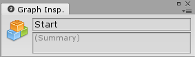
You can ignore the input and output port definitions below. They are only used for Super Units, not for Flow States.
Last but not least, the graph is pre-populated with 3 events. On Enter State gets called when an incoming transition leads to the parent state, and On Exit State gets called before the state is exited by one of its outgoing transitions. Update gets called at every frame while the state is active. Every event you add to a flow graph will only be listening while the parent state is active.
The rest of this graph works exactly like normal flow graphs. There are no restrictions on the units that can be used.
Super States
Super states are created and edited exactly like flow states. The major difference, of course, is that their graph is not a flow graph, but another state graph. When super states are entered, all the start states of their nested graph get entered. When super states are exited, every state and transition of the nested graph is made inactive.
流程态&超级态
在开始手册的这部分之前,我们假设您已经阅读了介绍,熟悉基本概念,并且已经创建过状态机。您还应该掌握如何使用流程图,因为它们在状态图中随处可见。
在这一点上,应该有一个具有单个起始节点的状态图。
状态
状态是一种自包含的行为,它告诉对象当它处于特定状态时它应该如何表现。它们通常用于人工智能(AI)行为或对象或场景结构。
例如,一个敌军NPC的状态机可以有4个状态,“巡逻”、“追赶”、“攻击”和“逃跑”,而一个门的状态机可以有3个状态,“锁定”、“解锁”和“打开”。
在Bolt,有两种大的状态类型。
流程态:包含嵌套流程图的状态。这意味着您可以使用每个状态中的前一节中的所有单元和连接。您创建的大多数状态将是流程态。
超级态:包含另一个嵌套状态图的状态。它们允许创建分层有限状态机(HSFM),即状态机内的状态机。它们对于高级重用和图的组织是有用的。
这两种类型的状态都是“巢穴'”,这意味着它们的工作方式与机器完全一样:它们的子图既可以嵌入,也可以从宏引用。他们从检视和举止都是一样的。
状态被转换连接在一起。我们将在下一篇文章中了解他们。现在,让我们关注状态本身。
创建状态
若要显示状态创建菜单,只需右击空网格中的任意位置即可。接下来,只需选择创建流程态。
就像流程图中的单元一样,新状态被调暗,因为它从未被输入。如果您不想要这种行为,可以禁用工具栏中的“DIM”。
起始状态(们)
您可以通过选择一个或多个起始状态来选择在哪个状态下图开始。要做到这一点,只需右键单击状态并选择切换开始。开始状态会以绿色突出显示。
与大多数有限状态机不同,Bolt允许多个启动状态。这意味着你可以在同一个图上运行并行的FSM(有限状态机)或者甚至在某个点上加入。然而,通常情况下,只需要一个启动状态。
任意状态
您可以使用任意状态触发到其他状态的转换,而不用管当前处于哪个状态。但是,此状态不能接收任何转换或执行任何操作。
阅读状态
让我们来看看一个状态的剖析。
状态的顶部是它的标题。它显示了它的嵌套图的标题和摘要。这些对功能没有影响,它们只是你识别和评论状态的一种方式。通过它的小流程图图标可以看出它是一个流程态。
你会发现,不同于单元,状态本身并不多。他们的检视器看起来和机的检视器完全一样。您可以选择状态嵌套图的源,并通过单击编辑图按钮打开它。您还可以双击状态节点打开它的嵌套图。
流程态
作为流程态的主体,您看到的是嵌套流图中使用的所有事件的列表。默认情况下,为方便期间,使用进入状态、 更新和状态改变事件创建新的流程态,但如果不需要这些流程态,则可以删除这些流程态,并添加所需的任何其他事件。
让我们双击状态打开它。
在左上角的导航板中,你可以看到,我们现在处于我们的游戏对象的状态图内,在其实状态中。
您可以在任何时候使用工具栏的这部分来导航回父图。
在图检视器的顶部,当您没有选择节点时,您可以编辑该状态的标题和摘要。
您可以忽略下面的输入和输出端口定义。它们仅用于超级单元,而不是用于流程态。
最后但并非最不重要的是,图表预先填充了3个事件。在传入的转换导致父状态时调用进入状态,并在退出状态由其输出转换之一退出之前调用退出状态。在状态激活时,在每个帧调用更新。添加到流图中的每个事件只会在父状态激活时时侦听。
此图的其余部分与正常流程图完全一样。对可以使用的单元没有限制。
超级态
超级态被创建和编辑与流程态完全一样。当然主要的区别是他们的图不是流程图,而是另一个状态图。当进入超级状态时,进入它们的嵌套图的所有起始状态。当退出超级态时,每个状态和嵌套图的转换都是不活动的。
翻译:追风团长
2018.7.10
