
因为手上只有9341屏修改了国外站点一个感觉是eps32的基础教学源码,以下是站的译文,代码修改为适应9341屏.其他未变.
此 ESP32-CAM 项目介绍了如何使用带有 TFT 显示屏的 ESP32-CAM 来显示CAM捕获的图片。我们已经多次介绍了如何在不同的项目中使用 ESP32-CAM,并介绍了如何在机器学习项目中使用 ESP32-CAM。即我们可以将 ESP32-CAM 与 Web 服务器配合使用来显示图片,在这篇文章中,我们也想介绍如何在 TFT(ILI9341) 屏幕上显示图片。因此,我们希望将 ESP32-CAM 拍摄的照片直接显示在显示屏上。在这种情况下,我们使用ILI9341显示屏,无论如何,如果您愿意,可以选择不同的TFT
ESP32-CAM 与 TFT 项目概述
要生成此项目,您将需要以下组件:
§ ESP32- CAM
§ 液晶显示器 (ILI9341)
§ 按钮(用于拍照)
§ FTDI232 用于对 ESP32-CAM 进行编程
该项目以这种方式工作:
§ 使用按钮,我们拍摄照片(就像在真实相机中发生的那样)
§ 拍摄照片后,ESP32 会在 TFT 上显示该照片
This is ESP32-cam如何将 ESP32-CAM 连接到 TFT 显示屏
这是带有TFT的ESP32-CAM接线图:
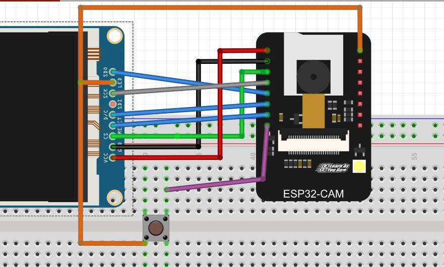
下表显示了 ESP32-CAM 引脚和 9341 引脚:
ESP32-CAM TFT (9341)
15 MOSI
13 CLK
12 CS
14 DC
2 RESET
显示从 ESP32-CAM 到 TFT 显示屏的图像
#include <Arduino.h>
#include <Wire.h>
#include <SPI.h>
#include <Adafruit_GFX.h> // Core graphics library
#include <Arduino_GFX_Library.h>
#include <TJpg_Decoder.h>
#include "esp_camera.h"
#define CAMERA_MODEL_AI_THINKER // Has PSRAM
#include "camera_pins.h"//找一个cam的camera_pins.h文件放入目录下
//以下引脚都可以成对配置,根据你的显示屏引脚位置自行选择,注意部分引脚不能混用.320*240
#define TFT_CS 12//2//13//15
#define TFT_RST 2//14//2
#define TFT_DC 14//15//14//0
#define TFT_MOSI 15//13//15//13//23
#define TFT_SCK 13//2//12//0//14//18
#define TFT_MISO 16//12//19
#define PIN_BTN 4
Arduino_ESP32SPI bus = Arduino_ESP32SPI(TFT_DC, TFT_CS, TFT_SCK, TFT_MOSI, TFT_MISO);
Arduino_ILI9341 tft = Arduino_ILI9341(&bus, TFT_RST);
bool tft_output(int16_t x, int16_t y, uint16_t w, uint16_t h, uint16_t* bitmap)
{
// Stop further decoding as image is running off bottom of screen
if ( y >= tft.height() ) return 0;
tft.draw16bitRGBBitmap(x, y, bitmap, w, h);
// Return 1 to decode next block
return 1;
}
void init_camera() {
camera_config_t config;
config.ledc_channel = LEDC_CHANNEL_0;
config.ledc_timer = LEDC_TIMER_0;
config.pin_d0 = Y2_GPIO_NUM;
config.pin_d1 = Y3_GPIO_NUM;
config.pin_d2 = Y4_GPIO_NUM;
config.pin_d3 = Y5_GPIO_NUM;
config.pin_d4 = Y6_GPIO_NUM;
config.pin_d5 = Y7_GPIO_NUM;
config.pin_d6 = Y8_GPIO_NUM;
config.pin_d7 = Y9_GPIO_NUM;
config.pin_xclk = XCLK_GPIO_NUM;
config.pin_pclk = PCLK_GPIO_NUM;
config.pin_vsync = VSYNC_GPIO_NUM;
config.pin_href = HREF_GPIO_NUM;
config.pin_sscb_sda = SIOD_GPIO_NUM;
config.pin_sscb_scl = SIOC_GPIO_NUM;
config.pin_pwdn = PWDN_GPIO_NUM;
config.pin_reset = RESET_GPIO_NUM;
config.xclk_freq_hz = 20000000;
config.pixel_format = PIXFORMAT_JPEG;
// if PSRAM IC present, init with UXGA resolution and higher JPEG quality
// for larger pre-allocated frame buffer.
if (psramFound()) {
config.frame_size = FRAMESIZE_QQVGA;
config.jpeg_quality = 10;
config.fb_count = 1;
Serial.println("PSRAM");
} else {
config.frame_size = FRAMESIZE_QVGA;
config.jpeg_quality = 12;
config.fb_count = 1;
}
#if defined(CAMERA_MODEL_ESP_EYE)
//pinMode(13, INPUT_PULLUP);
//pinMode(14, INPUT_PULLUP);
pinMode(15, INPUT_PULLUP);
pinMode(13, INPUT_PULLUP);
#endif
// camera init
esp_err_t err = esp_camera_init(&config);
if (err != ESP_OK) {
Serial.printf("Camera init failed with error 0x%x", err);
return;
}
sensor_t * s = esp_camera_sensor_get();
// initial sensors are flipped vertically and colors are a bit saturated
if (s->id.PID == OV2640_PID) {
Serial.println("PID");
s->set_vflip(s, 1); // flip it back
s->set_brightness(s, 2); // up the brightness just a bit
s->set_saturation(s, 0);
}
}
void setup() {
Serial.begin(9600);
Serial.println("ESP32-CAM Picture");
//tft.Init(INITR_BLACKTAB);
tft.begin();
tft.setRotation(1);
tft.fillScreen(MAGENTA);
init_camera();
pinMode(PIN_BTN, INPUT);
TJpgDec.setJpgScale(1);
// The decoder must be given the exact name of the rendering function above
TJpgDec.setCallback(tft_output);
}
void take_picture() {
Serial.println("Taking picture..");
camera_fb_t * fb = NULL;
fb = esp_camera_fb_get();
if (!fb) {
Serial.println("Camera capture failed");
}
uint16_t w = 0, h = 0;
TJpgDec.getJpgSize(&w, &h, fb->buf, fb->len);
Serial.print("- Width = "); Serial.print(fb->width); Serial.print(", height = "); Serial.println(fb->height);
Serial.print("Width = "); Serial.print(w); Serial.print(", height = "); Serial.println(h);
// Draw the image, top left at 0,0
TJpgDec.drawJpg(0, 0, fb->buf, fb->len);
}
void loop() {
while (true) {
int state = digitalRead(PIN_BTN);
if (state == HIGH) {
Serial.println("Button pressed");
take_picture();
}
delay(200);
}
}
如果您使用PlatformIO来开发此项目,则:
[env:esp32cam]
platform = espressif32
board = esp32cam
framework = arduino
lib_deps =
adafruit/Adafruit GFX Library @ ^1.10.5
adafruit/Adafruit ILI9341 and ILI9341 Library @ ^1.6.0
adafruit/Adafruit BusIO @ ^1.7.2
bodmer/TJpg_Decoder @ ^0.2.0
因此,我们将使用以下库:
§ Adafruit GFX Library
§ Adafruit BusIO
§ TJpg_Decoder
§ 关于camera_pins.h,请搜索存储盘,放入同一目录下..
您已经知道如何使用 ESP32-CAM 拍摄照片,现在我们只关注两个方面:
§ 如何将 ESP32-CAM 连接到 TFT 显示屏
§ 如何在TFT显示屏上显示图片
初始化 TFT 显示屏
这很简单,只需要几行代码:
#define TFT_MOSI 13 #define TFT_SCLK 14
#define TFT_CS 15 // Chip select control pin #define TFT_DC 2 // Data Command control pin #define TFT_RST 12
Arduino_ESP32SPI bus = Arduino_ESP32SPI(TFT_DC, TFT_CS, TFT_SCK, TFT_MOSI, TFT_MISO); Arduino_ILI9341 tft = Arduino_ILI9341(&bus, TFT_RST);
接下来,在方法中,代码初始化显示:
tft.initR(INITR_BLACKTAB); tft.setRotation(1); tft.fillScreen(MAGENTA);
如何在TFT上显示图片
这是最有趣的部分,因为在这里我们将在TFT显示屏上显示ESP32-CAM拍摄的照片。为此,我们将使用TJpg_Decoder库,因为它简化了我们的工作。首先,我们使用320×240等低分辨率,以便图像适合TFT。
下面的是库文件自带的示例。在 setup() 方法中,代码初始化库:
TJpgDec.setJpgScale(1);
// The decoder must be given the exact name of the rendering function above
TJpgDec.setCallback(tft_output);
定义用于显示图片的比例和调用方法:
bool tft_output(int16_t x, int16_t y, uint16_t w, uint16_t h, uint16_t* bitmap)
{
// Stop further decoding as image is running off bottom of screen
if ( y >= tft.height() ) return 0;
tft.drawRGBBitmap(x, y, bitmap, w, h);
// Return 1 to decode next block
return 1;
}
最后,当我们拍照时,代码运行渲染过程:
uint16_t w = 0, h = 0;
TJpgDec.getJpgSize(&w, &h, fb->buf, fb->len);
Serial.print("Width = "); Serial.print(w); Serial.print(", height = "); Serial.println(h);
// Draw the image, top left at 0,0
TJpgDec.drawJpg(0, 0, fb->buf, fb->len);
remember that contains the picture acquired while is the array length.
More useful resources:
获取图片数组的内容,数组长度。
处理按钮以拍照
最后一步 我们处理按钮 非常简单的步骤:
void loop() {
while (true) {
int state = digitalRead(PIN_BTN);
if (state == HIGH) {
Serial.println("Button pressed");
take_picture();
}
delay(200);
}
}
测试带 TFT 显示屏的 ESP32-CAM
现在是时候测试 ESP32-CAM 项目了。让我们捕捉一张图片。结果如下所示:

总结..
在本教程结束时,您已经学习了如何将 ESP32-CAM 与 TFT 显示器配合使用。在这个项目中,我们将 ESP32-CAM 与 9341 集成在一起,以显示捕获的图像。我们使用 ESP32-CAM 构建了一台简单的相机机器。
