
前言
在上篇中我们使用Grammar语法生成了建筑,那么按照[技术演讲]黑客帝国觉醒:生成世界(官方字幕)的顺序我们可以开始初步探索道路生成的部分了。在CitySample案例中,道路的部分使用Houdini构建。考虑到UE5越来越强大的几何体生成能力,本文使用UEC++对纯Editor环境下的几何体生成进行了尝试,通过使用者自定义输入的样条自动化生成道路和交汇路口。
参考
在技术方案收集阶段我发现了这样一款插件[Interactive Procedural City Generator | Fab](https://www.fab.com/listings/a41732dd-26f2-49e1-9f76-2167934651c2)它(以下按官方简称为IPCC)使用了纯蓝图以ScriptableTool的形式提供了一系列道路、城区生成工具。
FAB上的IPCC插件
听起来非常美好,有人已经用蓝图做出了所有的内容。但只要打开就会发现它和UltraDynamicSky插件一样,已经属于在挑战蓝图上限的级别了(技术美术干活就是猛),想改动、拓展有巨大的代价,编译、运行也较为迟缓。但它好在证明了这条技术路径是可行的,对于部分问题的解决也提供了一些思路。下面我们具体看一下我们在学习它的基础上,希望改善它下面两方面的问题:
运行效率:受制于蓝图本身无法支持复杂数据结构,在生成内容方面基本都是用添加Component-使用Component-删除Component的路线。很大程度上只使用了Component里某一个成员类的功能,却使得这个过程性能负担非常重,在较大的构筑时的性能消耗无法忽视。由于蓝图无法使用Subsystem,数据的集中管理非常困难,需要使用类似图结构进行大范围遍历实现连锁更新,更加重了系统的运行负担。
系统相容:他的生成逻辑受到Houdini影响很大,更多偏向于蓝图生成点数据,没有使用UE的PCG框架,整体较为封闭。换句话说,所有生成内容耦合性很高,生产流程高度串行,难以进行团队协作开发。
那么对应的,我想做的内容就更多体现在:
提升效率:更多使用C++提供的数据结构、算法的便利,使用更轻、更快的结构实现建设功能。
适配PCG:提供PCG框架友好的接口、数据,提高整个工作流程的并行性。
本文作为初步尝试,主要工作集中在提升效率上,对PCG的适配会在后续文章中分享。
项目代码
道路的程序化生成主要以代码为主,这方面天然缺少PCG的直观可视化。因此本文还是以公开工程的方式提供源码,和[UE5]CitySample复刻计划(1)-PCGGrammar尝试一样,本文对应的[项目GitHub](https://github.com/jiadevr/PCGDemo)使用5.6.1源码编译版本创建,需要C++编译环境。
讨论什么问题
从IPCC让人生畏的蓝图也可以知道,道路生成涉及的逻辑非常庞杂,在有限的篇幅内很难面面俱到,因此本文从下面几个关键问题的解决展开,分享在开发过程的经验:
框架设计和类的分工
生成思路
多样条线自动交点判定
交汇路口轮廓生成
道路生成
其他
框架设计和类的分工
从IPCC的生成过程来看,整体的生成流程是:使用ScriptableTool输入数据-道路生成-地块生成-建筑生成。那么对应的我们需要收集用户数据、管理各种Actor对象的生成和更新、为其它模块提供接口和数据,由于C++中可以使用EditorSubsystem,可以直接把Manager的职责规划到Subsystem中,使用多个Subsystem完成这个操作。
对于用户输入这一核心数据建立主Subsystem,负责用户输入数据的读取和保存;对于各种生成内容,我们分别设立Subsystem实现逻辑的隔离,避免生成一个“大而全”的类,便于后期的单独维护和升级。
再聚焦到单个对象生成的过程,出于同样的目的,我们不希望一个类包揽所有工作,需要对生成过程进行细化。这方面我们可以参考设计行业的分工思路:由用户/主Subsystem完成场景道路规划(规划院画规划方案)——由生成Subsystem确定具体生成的坐标和基本信息(设计院画施工方案)——由实际Actor确定具体场景中如何生成(施工方现场施工),实现逐步细化,在后续方案更改时也可以有效控制更改范围。
为了更好地发挥组合模式的作用,我们使用ActorComponent作为这个施工方,由它指挥UDynamicMeshComponent完成实际几何体构建,因此我们整体的框架分工如下所示:
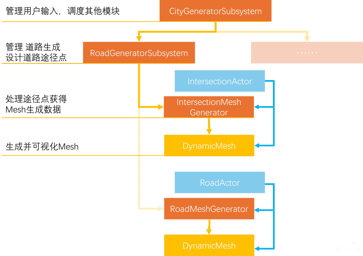
整体生成框架
整体来看,采用反向控制、依赖注入和观察者模式,数据流逐层细化,上层结构不必关心下层如何进行具体的细化,但可以通过下层的接口获得关键数据。
生成思路
从IPCC中我们可以看到交汇点和道路的核心函数:AppendSimpleExtrudePolygon——也就是我们在建模软件中的挤出操作;AppendSweepPolygon——也就是我们在建模软件中的扫描操作。
对于挤出操作,我们只需要提供二维截面和固定的挤出高度,难点在二维截面的生成。对于扫描操作,我们需要提供二维截面和扫描路径(TArray),难点在获取扫描路径。
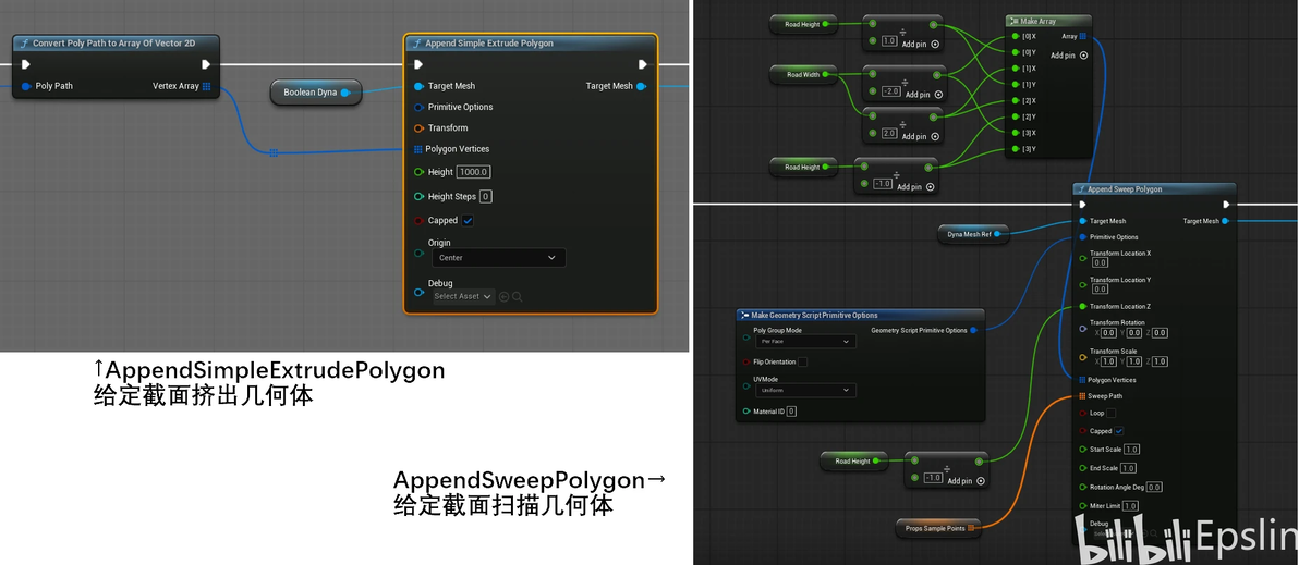
交汇点和道路生成的核心节点
交汇点的二维截面可以看作是对道路相交点的裁剪合并,道路的扫描模型可以看作整条Spline去除相交点。因此从生成顺序上来看我们可以先生成交汇路口,使用交汇路口对整条曲线裁切,获得分段的道路。
同时我们还可以注意到,道路的生成需要FTransform数组,这意味着我们需要把样条细分成多段线,我们可以使用USplineComponent::ConvertSplineToPolyLineWithDistances()函数进行自动切割,函数会以引用形式返回转换获得的多段线点和多段线点距离起点的长度(不是每段长度,因此不需要重复求前缀和数组)。为了同一称呼,下面我们称样条转换PolyLine获得的分段为Segment;
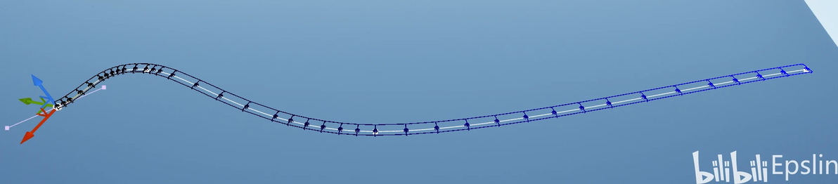
如果对切分结果直接进行可视化,我们会发现它非常智能地在样条Tangent变化大的区域布点更多,在趋近直线的区域布点更少,如下图所示:
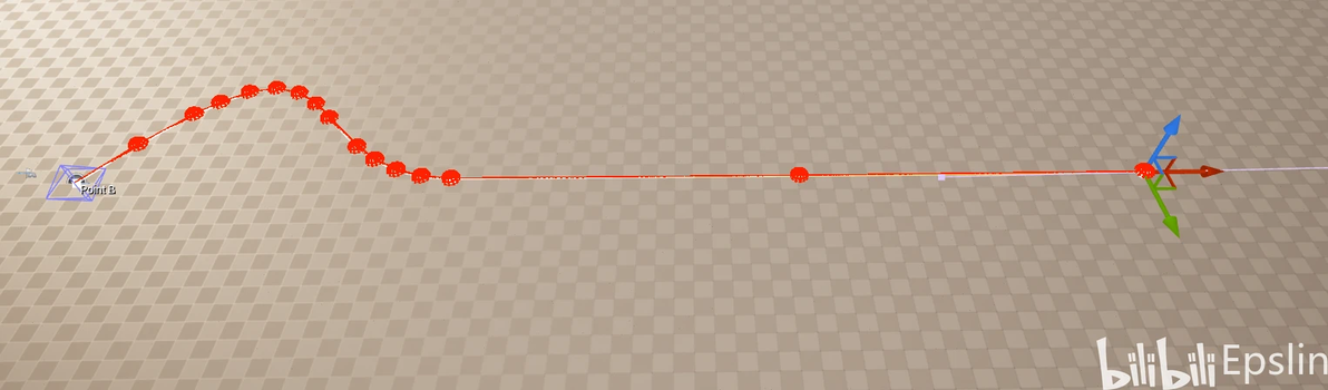
样条的细分点情况
对于通常情况,这是一种优化,意味着要记录的数据点更少。但结合我们之前的生成逻辑就会知道,如果在这些区域存在交汇点,那么为数不多的Segment就会被直接裁切导致分段被清空,对于后续生成连续道路并不是好消息,因此我们需要对样条进行重采样,在直线部分增加分段数。为此我们可以测试每一段分段长度,如果超过给定阈值长度就需要在其中加入点。部分代码如下:
TArray URoadGeneratorSubsystem::ResampleSpline(const USplineComponent* TargetSpline)
{
	TArray Results;
	if (nullptr == TargetSpline || TargetSpline->GetNumberOfSplinePoints() GetSplineLength();
	TArray PolyLineEndPointLoc;
	TArray PolyLineLengths;
	//曲线,该函数返回闭合样条返回段,Distance数组是到每一个端点处的长度(类似前缀和)
	TargetSpline->ConvertSplineToPolyLineWithDistances(ESplineCoordinateSpace::World, PolyLineSampleDistance,
	                                                   PolyLineEndPointLoc, PolyLineLengths);
	TMap> SegmentsToSubdivide;
	Results.Reserve(PolyLineEndPointLoc.Num());
	Results.Emplace(
		TargetSpline->GetTransformAtDistanceAlongSpline(PolyLineLengths[0], ESplineCoordinateSpace::World,
		                                                true));
	for (int i = 1; i < PolyLineLengths.Num(); ++i)
	{
		Results.Emplace(
			TargetSpline->GetTransformAtDistanceAlongSpline(PolyLineLengths[i], ESplineCoordinateSpace::World,
			                                                true));
		if (PolyLineLengths[i] - PolyLineLengths[i - 1] > SegmentMaxDisThreshold)
		{
			//以该点为起点的位置需要插入元素
			SegmentsToSubdivide.Add(i - 1);
		}
	}
	if (SegmentsToSubdivide.IsEmpty())
	{
		return Results;
	}
	//如果需要处理
	for (TPair>& TargetSegment : SegmentsToSubdivide)
	{
		const int32 SegmentIndex = TargetSegment.Key;
		const float OriginalSegmentLength = PolyLineLengths[SegmentIndex + 1] - PolyLineLengths[SegmentIndex];
		int32 TargetSubdivisionNum = FMath::CeilToInt32(OriginalSegmentLength / SegmentMaxDisThreshold);
		double TargetSubdivisionLength = OriginalSegmentLength / TargetSubdivisionNum;
		TArray SubdivisionPoints;
		for (int32 j = 1; j < TargetSubdivisionNum; j++)
		{
			float DisToSubdivisionPoint = static_cast(j * TargetSubdivisionLength + PolyLineLengths[
				SegmentIndex]);
			TargetSegment.Value.Emplace(
				TargetSpline->GetTransformAtDistanceAlongSpline(DisToSubdivisionPoint, ESplineCoordinateSpace::World));
		}
	}
	//FTransform为非POD对象,不能直接内存拷贝,下面这个函数意义不大
	/*TArray> ContinuousIndexSeries = GetContinuousIndexSeries(
		BreakPoints, static_cast(PolyLineLengths.Num() - 1));*/
	InsertElementsAtIndex(Results, SegmentsToSubdivide);
	return Results;
}需要特别注意FTransform不是POD对象,不能直接使用FMemoryCopy拷贝过来。细分之后的效果如下图所示,有了足够的分段,我们就可以开始求在哪些位置生成交汇点了。
在直线段增加细分
多样条线自动交点判定
在IPCC中交点需要手动使用PCC_Add_Interesction添加,这种方法虽然稍显繁琐但是有效规避了大量样条段求交的计算量。既然我们已经到了C++中,就可以通过四叉树来解决这一问题。使用四叉树可以为我们筛选“可能相交”的Segments,进行首次剪枝,避免逐个遍历计算交点,提升计算交点的效率。
UE中已经为我们提供了一种四叉树,即模板类TQuadTree,在构造时需要传入三个参数实例化类型、整体覆盖范围和最小节点边长。也就是说,它通过边长来控制四叉树最大深度,这种方式相较直接控制深度来说使用起来更方便,但TQuadTree本身没有提供直接获取某层全部元素的方法,在Debug上的可视化程度比较低,如果对可视化有强烈需求可以以参考天空游荡的鱼-【UE4】数据结构之四叉树-概念引入及开发动态四叉树演示项目及该UP在AboutCG的免费课程。
说回到TQuadTree,在使用中我们首先遍历所有样条获得覆盖的最大范围使用FBox2D表示,设定一个MinmumQuadSize,这个值可以和我们的细分分段长度近似,在UE中实现中跨格子的内容会被挂载到上一层的节点中,对搜索结果基本没有影响。然后我们需要一个用于描述Segment的结构来实例化四叉树模板,并把要查询的元素按照这个结构依次插入。
对于这个结构,我们希望它能完成以下任务:
负载所属的Spline信息,但不希望直接影响Spline的生命周期,避免编辑器中的Spline无法被GC、删除时出现警告。所以可以使用TWeakObjectPtr模板类,传入USplineComponent进行模板实例化。
分段信息:它属于所在Spline的哪一个分段、Spline的全部分段数、全局分段ID,这里我们依然可以借鉴TWeakObjectPtr,使用一个递增的uint32类型的GlobalIndex作为全局ID。
分段端点坐标:分段的起始坐标和终止坐标。
综上,我们形成的结构体如下:
USTRUCT(BlueprintType)
struct FSplinePolyLineSegment
{
	GENERATED_BODY()
	FSplinePolyLineSegment()
	{
		//SegmentGlobalIndex++;
	}

public:
	FSplinePolyLineSegment(TWeakObjectPtr InSplineRef, uint32 InSegmentIndex,
	                       uint32 InLastSegmentIndex,
	                       const FTransform& InStartTransform,
	                       const FTransform& InEndTransform) : OwnerSpline(InSplineRef),
	                                                           SegmentIndex(InSegmentIndex),
	                                                           LastSegmentIndex(InLastSegmentIndex),
	                                                           StartTransform(InStartTransform),
	                                                           EndTransform(InEndTransform)
	{
		GlobalIndex = SegmentGlobalIndex++;
	};

	~FSplinePolyLineSegment()
	{
		OwnerSpline = nullptr;
	}

	static void ResetGlobalIndex() { SegmentGlobalIndex = 0; }
	/**
	 * 所属的Spline信息
	 */
	UPROPERTY()
	TWeakObjectPtr OwnerSpline = nullptr;

	/**
	 * 当前PolyLine的SegmentIndex
	 */
	uint32 SegmentIndex = 0;

	/**
	 * 所在Spline被切割出的Segment总数
	 * 这个值是为了排除ClosedLoop最后一点和第一点连接的情况,这边是为了多线程可以不访问Spline对象额外记录的
	 */
	uint32 LastSegmentIndex = 0;

	/**
	 * Segment起点,世界空间位置;
	 */
	FTransform StartTransform = FTransform::Identity;

	/**
	 * Segment终点,世界空间位置
	 */
	FTransform EndTransform = FTransform::Identity;

	/**
	 * 返回Segment全局ID,用于区分不同Segment
	 * @return 返回ID值
	 */
	uint32 GetGlobalIndex() const { return GlobalIndex; }

protected:
	/**
	 * 全局Segment递增序号
	 */
	static uint32 SegmentGlobalIndex;
	/**
	 * 自身的Segment编号
	 */
	uint32 GlobalIndex = 0;
};有了结构体,下面我们就该进行四叉树构建和元素插入了,四叉树的元素插入使用Insert()函数,需要传入信息和FBox2D表示的覆盖范围,我们既然已经使用多段线描述了样条,自然也就使用每一段的起点终点构建范围。这部分的代码片段如下:
AllSegments.Reserve(SplineSegmentsInfo.Num() * 2);
	FBox2D TotalBounds(ForceInit);
	for (const auto& SegmentsOfSingleSpline : SplineSegmentsInfo)
	{
		if (!SegmentsOfSingleSpline.Key.IsValid())
		{
			continue;
		}
		TArray Segments = SegmentsOfSingleSpline.Value;
		for (const FSplinePolyLineSegment& Segment : Segments)
		{
			TotalBounds += FVector2D(Segment.StartTransform.GetLocation());
			TotalBounds += FVector2D(Segment.EndTransform.GetLocation());
			AllSegments.Emplace(Segment);
		}
	}

	SplineQuadTree = TQuadTree(TotalBounds, MinimumQuadSize);
	for (const auto& SegmentWithIndex : AllSegments)
	{
		FBox2D SegmentBounds(ForceInit);
		SegmentBounds += FVector2D(SegmentWithIndex.StartTransform.GetLocation());
		SegmentBounds += FVector2D(SegmentWithIndex.EndTransform.GetLocation());
		SplineQuadTree.Insert(SegmentWithIndex, SegmentBounds);
	}

UE_LOG(LogTemp, Display, TEXT("Finish Insert To QuadTree"));再下一步就是进行查询了,TQuadTree提供了GetElements()进行查询并计算交点,我们依然使用遍历分段的方式逐一去占据了相同四叉树节点的Segment、计算交点,但可以使用备忘录技巧避免重复遍历,查询并计算交点的代码片段如下:
	//用于接收四叉树查询结果
	TArray OverlappedSegments;
	//用于缓存四叉树处理过的样条分段,使用Segment的GlobalIndex
	TSet> ProcessedPairs;
	for (int i = 0; i < AllSegments.Num(); ++i)
	{
		FBox2D SegmentQueryBounds;
		SegmentQueryBounds += FVector2D(AllSegments[i].StartTransform.GetLocation());
		SegmentQueryBounds += FVector2D(AllSegments[i].EndTransform.GetLocation());
		//扩大范围
		SegmentQueryBounds = SegmentQueryBounds.ExpandBy(10.0f);
		//Reset不缩小内存
		OverlappedSegments.Reset();
		SplineQuadTree.GetElements(SegmentQueryBounds, OverlappedSegments);
		for (const FSplinePolyLineSegment& OverlappedSegment : OverlappedSegments)
		{
			//排除自己
			if (AllSegments[i].GetGlobalIndex() == OverlappedSegment.GetGlobalIndex())
			{
				continue;
			}
			//排除相连的同一样条的Segment
			if (AllSegments[i].OwnerSpline == OverlappedSegment.OwnerSpline)
			{
				const uint32 IndexGap = AllSegments[i].SegmentIndex > OverlappedSegment.SegmentIndex
					                        ? AllSegments[i].SegmentIndex - OverlappedSegment.SegmentIndex
					                        : OverlappedSegment.SegmentIndex - AllSegments[i].SegmentIndex;
				if (IndexGap  IndexPair;
			if (AllSegments[i].GetGlobalIndex() < OverlappedSegment.GetGlobalIndex())
			{
				IndexPair.Key = AllSegments[i].GetGlobalIndex();
				IndexPair.Value = OverlappedSegment.GetGlobalIndex();
			}
			else
			{
				IndexPair.Key = OverlappedSegment.GetGlobalIndex();
				IndexPair.Value = AllSegments[i].GetGlobalIndex();
			}
			//已经处理过跳过
			if (ProcessedPairs.Contains(IndexPair))
			{
				continue;
			}
			ProcessedPairs.Emplace(IndexPair);
			FVector2D IteratorSegmentStart = FVector2D(AllSegments[i].StartTransform.GetLocation());
			FVector2D IteratorSegmentEnd = FVector2D(AllSegments[i].EndTransform.GetLocation());
			FVector2D TestingSegmentStart = FVector2D(OverlappedSegment.StartTransform.GetLocation());
			FVector2D TestingSegmentEnd = FVector2D(OverlappedSegment.EndTransform.GetLocation());
			FVector2D IntersectionLoc2D;
			if (!URoadGeometryUtilities::Get2DIntersection(IteratorSegmentStart, IteratorSegmentEnd,
			                                               TestingSegmentStart, TestingSegmentEnd,
			                                               IntersectionLoc2D))
			{
				continue;
			}
			FVector FlattedIntersectionLoc = FVector(IntersectionLoc2D, 0.0);
			//检查相近点
			bool bCanMerge = false;
			for (FSplineIntersection& Result : Results)
			{
				//相当于用空间关系进行交点索引
				if (FVector::DistSquared2D(Result.WorldLocation, FlattedIntersectionLoc) < MergeThreshold *
					MergeThreshold)
				{
					//AddSplineToOldIntersectionData
					Result.IntersectedSplines.Emplace(OverlappedSegment.OwnerSpline);
					Result.IntersectedSegmentIndex.Emplace(OverlappedSegment.SegmentIndex);
					bCanMerge = true;
					break;
				}
			}
			if (!bCanMerge)
			{
				//首次添加需要加两个Segment信息
				TArray> IntersectedSplines{
					AllSegments[i].OwnerSpline, OverlappedSegment.OwnerSpline
				};
				TArray IntersectedSegmentIndex{AllSegments[i].SegmentIndex, OverlappedSegment.SegmentIndex};
				FSplineIntersection
					NewIntersection(IntersectedSplines, IntersectedSegmentIndex, FlattedIntersectionLoc);
				//AddSplineToNewIntersectionData
				Results.Emplace(NewIntersection);
			}
}交点计算中,因为我们已经将Spline转化成了多段线并使用FSplinePolyLineSegment表示,在计算过程中只需要使用快速的线段相交判断即可,即上面代码片段的URoadGeometryUtilities::Get2DIntersection(),具体代码如下:
bool URoadGeometryUtilities::Get2DIntersection(const FVector2D& InSegmentAStart, const FVector2D& InSegmentAEnd,const FVector2D& InSegmentBStart, const FVector2D& InSegmentBEnd,FVector2D& OutIntersection)
{
	//快速排斥测试
	if (FMath::Max(InSegmentAStart.X, InSegmentAEnd.X) < FMath::Min(InSegmentBStart.X, InSegmentBEnd.X) ||
		FMath::Max(InSegmentBStart.X, InSegmentBEnd.X) < FMath::Min(InSegmentAStart.X, InSegmentAEnd.X) ||
		FMath::Max(InSegmentAStart.Y, InSegmentAEnd.Y) < FMath::Min(InSegmentBStart.Y, InSegmentBEnd.Y) ||
		FMath::Max(InSegmentBStart.Y, InSegmentBEnd.Y) < FMath::Min(InSegmentAStart.Y, InSegmentAEnd.Y))
	{
		return false;
	}

	// 计算线段AB和CD的参数方程交点
	FVector2D VectorA = (InSegmentAEnd - InSegmentAStart);
	FVector2D VectorB = (InSegmentBEnd - InSegmentBStart);
	FVector2D VectorABStart = InSegmentBStart - InSegmentAStart;
	//叉积获得AB逆时针夹角的Sin值,Sin值为0时两向量平行或共线
	float Denominator = FVector2D::CrossProduct(VectorA, VectorB);
	if (FMath::IsNearlyZero(Denominator))
	{
		return false;
	}
	//直线参数方程
	//(X0,Y0)=AStart+t*VectorA=BStart+S*VectorB
	//使用三角形相似计算比值
	float t = FVector2D::CrossProduct(VectorABStart, VectorB) / Denominator;
	float s = FVector2D::CrossProduct(VectorABStart, VectorA) / Denominator;

if (t >= 0.0f && t = 0.0f && s 如果不进行分段,那么我们就不得不对每条样条线的ControlPoints进行划分,并按照三次贝塞尔线段使用牛顿法进行计算,由于迭代的需求,它的耗时显著更长。这部分代码在本项目中中提供了bool URoadGeometryUtilities::Get2DIntersection(USplineComponent* TargetSplineA, USplineComponent* TargetSplineB,TArray& IntersectionsIn2DSpace)为签名的重载,感兴趣的朋友可以自行尝试。
回到上面线段求交的结果,它会返回一个FSplineIntersection类型的数组,这个结构体记录了交点位置、相交样条线、相交样条线的SegmentGlobalID,相当于焦点核心内容的提取。内容如下所示:
USTRUCT(BlueprintType)
struct FSplineIntersection
{
	GENERATED_BODY()

public:
	FSplineIntersection()
	{
	}

	FSplineIntersection(const TArray>& InIntersectedSplines,
	                    const TArray& InIntersectedSegmentIndex,
	                    const FVector& InIntersectionPoint) : IntersectedSplines(
		                                                          InIntersectedSplines),
	                                                          IntersectedSegmentIndex(InIntersectedSegmentIndex),
	                                                          WorldLocation(InIntersectionPoint)
	{
	}

	~FSplineIntersection()
	{
		IntersectedSplines.Empty();
	}


	/**
	 * 相交的样条线引用
	 */
	TArray> IntersectedSplines;
	/**
	 * 样条线相交处的SegmentIndex
	 */
	//UPROPERTY(BlueprintReadOnly, VisibleInstanceOnly)
	TArray IntersectedSegmentIndex;
	/**
	 * 交点位置
	 */
	UPROPERTY(BlueprintReadOnly, VisibleInstanceOnly)
	FVector WorldLocation = FVector::Zero();
};
交汇路口轮廓生成
完成交点获取之后,我们已经可以获得交汇点Actor的放置位置,下面我们需要从相交的样条中制作截面轮廓、挤出几何体。正如前文所说,交汇路口生成的关键就在于交汇轮廓。
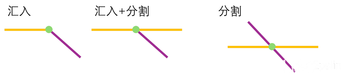
在上面的交点计算中我们获得了交点结构体FSplineIntersection,但这个结构体只指示了哪些样条线相交在哪,并没有具体的Segment描述。也就是说,具体这个位置时是样条单纯汇入还是样条被交汇点截成两段并没有描述。作为“施工图”的一部分,RoadMeshGeneratorSubsystem显然要提供这些信息。因此URoadGeneratorSubsystem::TearIntersectionToSegments()函数应运而生,这个函数处理前面获得的FSplineIntersection并采样样条,根据采样结果判断样条剩余长度。当样条剩余长度小于阈值时,认为道路汇入路口;大于阈值时认为道路被路口截断。基于上述条件,我们有了下面三种交汇点模型:
交汇点基本模型
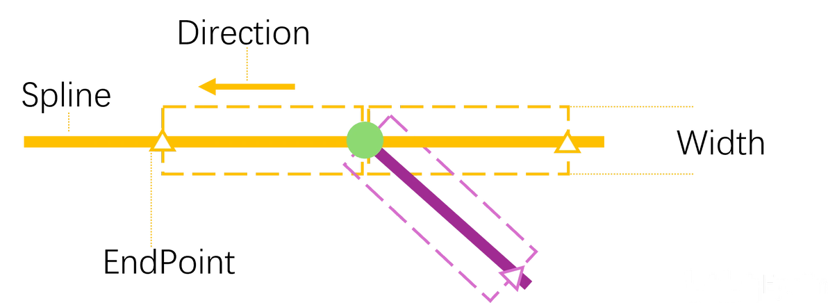
我们以交汇点(上图中绿色点)为分割点,它们进行切割,显然我们又需要一个新的结构来记录这种分段。由于交点位置已经被确定为IntersectionActor的位置,不需要额外记录,我们需要记录的内容包括:
所在样条(Spline):用于后续继续采样其他信息。
Segment终点(EndPoint):切割分段的起点是IntersectionActor的位置,终点需要额外记录。
汇入方向(Direction):样条的前进方向是由Segment终点指向交汇点还是由交汇点指向Segment终点,便于判断矢量方向。
道路宽度(Width),用于确定道路边线偏移值。
也就是说我们现在有这样一组数据,称之为FIntersectionSegment,可视化效果如下:
FIntersectionSegment示意图
结构体代码实现如下:
USTRUCT(BlueprintType)
struct FIntersectionSegment
{
	GENERATED_BODY()

public:
	FIntersectionSegment()
	{
	};

	FIntersectionSegment(TWeakObjectPtr& InOwnerSplines, const FVector& InIntersectionEndPointWS,
	                     bool bInIsFlowIn, float InRoadWidth) : OwnerSpline(InOwnerSplines),
	                                                            IntersectionEndPointWS(InIntersectionEndPointWS),
	                                                            bIsFlowIn(bInIsFlowIn), RoadWidth(InRoadWidth)
	{
	}

	~FIntersectionSegment()
	{
		OwnerSpline = nullptr;
	};

	/**
	 * 所属的SplineComponent
	 */
	UPROPERTY(VisibleInstanceOnly)
	TWeakObjectPtr OwnerSpline;
	/**
	 * 沿样条线方向的端点(交点为另一端点)
	 */
	UPROPERTY(BlueprintReadWrite, EditInstanceOnly)
	FVector IntersectionEndPointWS = FVector::Zero();
	/**
	 * 方向(驶入驶出),以Distance判定
	 */
	UPROPERTY(BlueprintReadWrite, EditInstanceOnly)
	bool bIsFlowIn = true;
	/**
	 * 道路宽度
	 */
	UPROPERTY(BlueprintReadWrite, EditInstanceOnly)
	float RoadWidth = 0;
};然后将有效的路口组合成FIntersectionSegment、将FIntersectionSegment按照顺时针顺序排序,函数如下:
bool URoadGeneratorSubsystem::TearIntersectionToSegments(
	const FSplineIntersection& InIntersectionInfo, TArray& OutSegments, float UniformDistance)
{
	if (InIntersectionInfo.IntersectedSplines.IsEmpty())
	{
		return false;
	}
	TArray> IntersectedSplines = InIntersectionInfo.IntersectedSplines;
	OutSegments.Reserve(IntersectedSplines.Num());
	OutSegments.Reset();

	for (int i = 0; i < IntersectedSplines.Num(); ++i)
	{
		if (!IntersectedSplines[i].IsValid())
		{
			return false;
		}
		USplineComponent* TargetSpline = IntersectedSplines[i].Pin().Get();
		float Distance = TargetSpline->GetDistanceAlongSplineAtLocation(InIntersectionInfo.WorldLocation,
		                                                                ESplineCoordinateSpace::World);
		//判断后边一段是不是在样条上
		const float DistanceOfNextPoint = Distance + UniformDistance;
		if (DistanceOfNextPoint < TargetSpline->GetSplineLength())
		{
			FVector FlowOutPointLoc = TargetSpline->GetLocationAtDistanceAlongSpline(
				DistanceOfNextPoint, ESplineCoordinateSpace::World);
			OutSegments.Emplace(FIntersectionSegment(IntersectedSplines[i], FlowOutPointLoc, false, 500.0f));
		}
		//判断前边一段是不是在样条上
		if (Distance > UniformDistance)
		{
			FVector FlowInPointLoc = TargetSpline->GetLocationAtDistanceAlongSpline(
				Distance - UniformDistance, ESplineCoordinateSpace::World);
			OutSegments.Emplace(FIntersectionSegment(IntersectedSplines[i], FlowInPointLoc, true, 500.0f));
		}
	}
	if (OutSegments.IsEmpty())
	{
		return false;
	}
	//根据顺时针顺序排序
	FVector IntersectionPoint = InIntersectionInfo.WorldLocation;
	OutSegments.Sort([&IntersectionPoint](const FIntersectionSegment& A, const FIntersectionSegment& B)
	{
		FVector ProjectedA = FVector::VectorPlaneProject((A.IntersectionEndPointWS - IntersectionPoint),
		                                                 FVector::UnitZ());
		FVector2D RelA{ProjectedA.X, ProjectedA.Y};
		FVector ProjectedB = FVector::VectorPlaneProject((B.IntersectionEndPointWS - IntersectionPoint),
		                                                 FVector::UnitZ());
		FVector2D RelB{ProjectedB.X, ProjectedB.Y};

		float AngleA = FMath::Atan2(RelA.Y, RelA.X);
		float AngleB = FMath::Atan2(RelB.Y, RelB.X);

		// 转换为[0, 2π)范围
		if (AngleA < 0) AngleA += 2 * PI;
		if (AngleB < 0) AngleB += 2 * PI;

		if (AngleA != AngleB)
		{
			return AngleA < AngleB; // 极角小的排在前面
		}
		else
		{
			// 角度相同,按距离排序(近的在前)
			return RelA.SizeSquared() < RelB.SizeSquared();
		}
	});
	return true;
}此时可以说我们获得了主要数据,可以将这份比较潦草的“概要施工图”传递给下一个环节及进行施工细化了。
基于之前我们在框架中的讨论,我们生成一个空的Actor,然后为他挂载用于“施工细化”的Component。对于交汇路口,其名称为RoadMeshGenerator,我们将上面排序后的FIntersectionSegment数组通过函数UIntersectionMeshGenerator::SetIntersectionSegmentsData(const TArray& InIntersectionData)传递给RoadMeshGenerator。
在RoadMeshGenerator中,我们需要完成的最重要内容就是生成路口之间的过渡线,对应实际中的转弯车道。由于在传入前我们已经把各个Segment终点按照顺时针排序,所以每条Segment必定和相邻的Segment相交。
至于过渡线的制作,根据IPCC中的算法,我们只需要设置一条弧线,连接相邻的两个端点,设置端点处Tangent为2倍的端点指向交点的矢量,然后再将弧线转变为多段线即可。
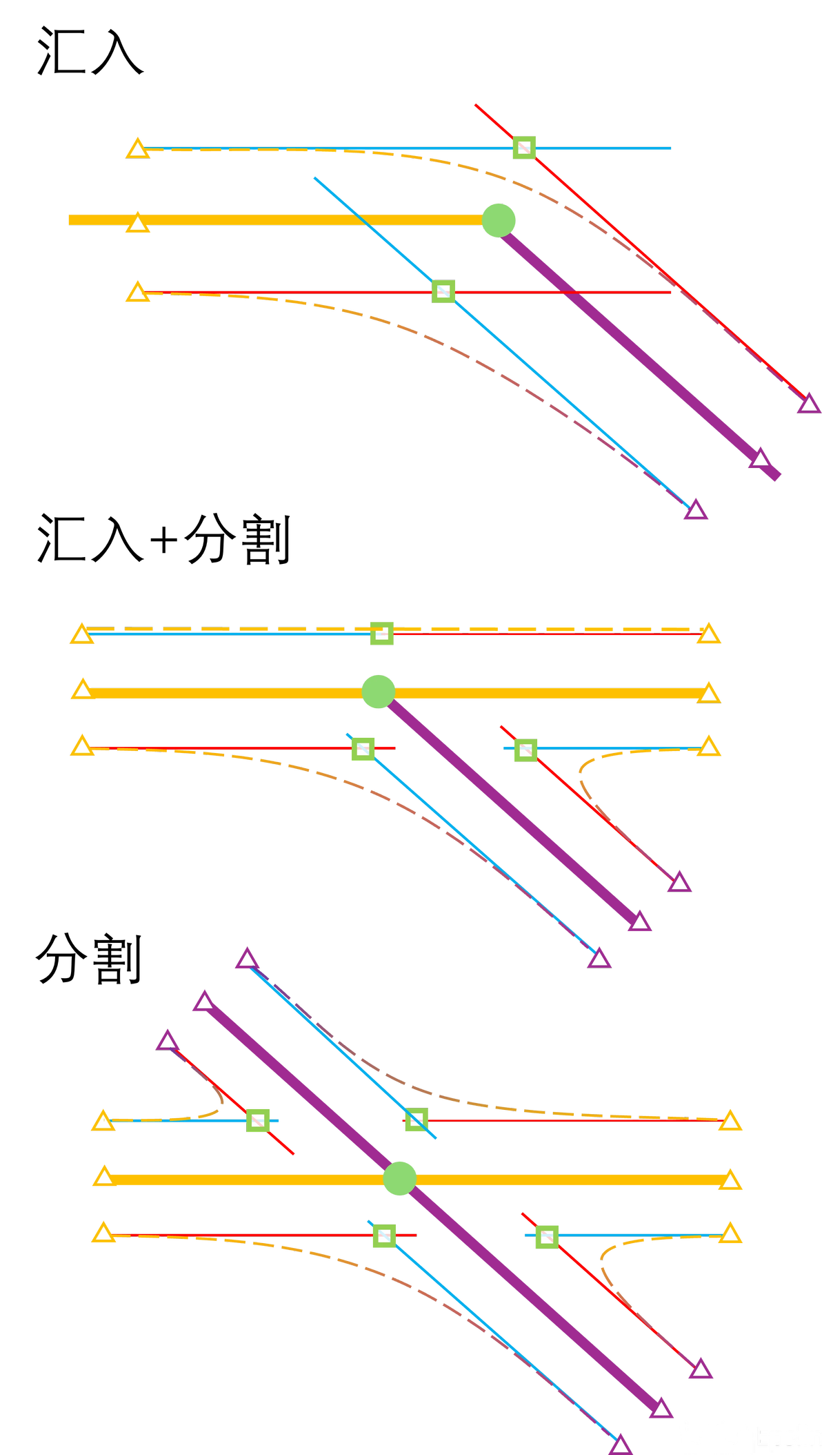
在实际操作中我们先根据道路宽度寻找道路的左右边界,为了便于后续处理,我们在计算时均先计算右侧再计算左侧,将端点保存到数组中。在计算交点时我们有如下计算模型:目标样条右边界和右邻居样条的左边界、目标样条左边界和左侧邻居的右边界。如下图所示:
交汇点基本模型绘制方式
在上图中列举了交汇点的三种基本模型连接线的绘制方式,其中红色表示端点->交点方向观察时道路右边线,蓝色表示端点->交点方向观察时道路左边线,绿色正方形表示相邻Segment边线的交点。在我们定义交点计算模型中,需要把相邻的红线和蓝线计算相交。直线相交的计算可以继续复用我们多段线相交的函数URoadGeometryUtilities::Get2DIntersection(),在遍历过程中依然使用备忘录方式以{MinIndex,MaxIndex}对的形式标记已经计算过交点的线段,但需要特别注意最后一段线段在计算时需要设置为{LastIndex,FirstIndex},否则可能无法正确连接,尤其是在汇入模型情况下,形成形如下图的错误
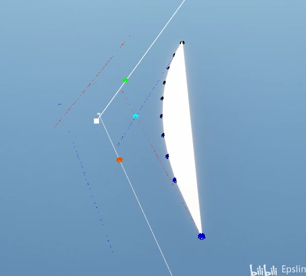
最后一段未计算导致的生成错误
获得交点之后我们就可以连接曲线获得平滑过渡,从USplineComponent中我们可以看到SplineComponent其实内部包含了Vector+Quat+Vector+Float四个曲线对象。对于我们的需求只需要位置和Tangent,只需要选择性构建一个FInterpCurveVector2D即可满足需求,相比PICC可以节省很多资源。
但另一方面,我们之前依仗的Spline转多段线函数USplineComponent::ConvertSplineToPolyLineWithDistances()是USplineComponent的成员函数,在FInterpCurveVector2D下无法调用。我们需要写一个手动点采样函数,好在对于只有两个控制点、长度也很短的过渡线这并不是难事。
交汇口截面二维坐标的整体代码片段如下:
TArray UIntersectionMeshGenerator::CreateExtrudeShape()
{
	OccupiedBox.Init();
	bool bShowDebug = !CVarHideGraphicDebug.GetValueOnGameThread();
	//保持整体连贯性,所有FVector转成2D计算
	TArray IntersectionConstructionPoints;
	AActor* Owner = GetOwner();
	if (nullptr == GetOwner())
	{
		UNotifyUtilities::ShowPopupMsgAtCorner("Error:Found Null Owner");
		return IntersectionConstructionPoints;
	}
	const int32 IntersectionSegmentNum = IntersectionsData.Num();
	IntersectionConstructionPoints.Reserve(IntersectionSegmentNum * 10);
	const FVector2D CenterLocation(Owner->GetActorLocation());
	//每个中心线生成左右两个线段,共4个端点
	TArray RoadEdgePoints;
	RoadEdgePoints.Reserve(IntersectionSegmentNum * 4);
	//为了让Segment可以相交,需要把线段延长
	static const double SegmentScalar = 2.0;
	//先计算Offset之后的点,先右后左
	for (int32 i = 0; i < IntersectionSegmentNum; i++)
	{
		const FVector2D CurrentSegmentEndPoint2D(IntersectionsData[i].IntersectionEndPointWS);
		if (bShowDebug)
		{
			//中心点显示流入为绿色,流出为橙色
			DrawDebugSphere(GetWorld(), IntersectionsData[i].IntersectionEndPointWS, 20.0f, 8,
			                (IntersectionsData[i].bIsFlowIn ? FColor::Green : FColor::Orange), true, -1, 0,
			                5);
		}
		const FVector2D VectorToCenter = FVector2D(CenterLocation - CurrentSegmentEndPoint2D);
		//const FVector2D FlowDir =(VectorToCenter /* (IntersectionsData[i].bIsFlowIn ? 1.0 : -1.0)*/).GetSafeNormal();

		FVector2D RightEdge = VectorToCenter.GetSafeNormal().GetRotated(90.0) * IntersectionsData[i].
			RoadWidth * 0.5;
		//以FlowDir为基准,右侧两个点
		FVector2D RightMid = CurrentSegmentEndPoint2D + RightEdge;
		FVector2D RightStart = RightMid - VectorToCenter * SegmentScalar;
		RoadEdgePoints.Emplace(RightStart);
		FVector2D RightEnd = RightMid + VectorToCenter * SegmentScalar;
		RoadEdgePoints.Emplace(RightEnd);
		if (bShowDebug)
		{
			//右侧红线
			DrawDebugDirectionalArrow(GetWorld(), FVector(RightStart, 0.0), FVector(RightEnd, 0.0), 100.0f, FColor::Red,
			                          true);
		}

		//以FlowDir为基准,左侧两个点
		FVector2D LeftMid = CurrentSegmentEndPoint2D + RightEdge * -1.0;
		FVector2D LeftStart = LeftMid - VectorToCenter * SegmentScalar;
		RoadEdgePoints.Emplace(LeftStart);
		FVector2D LeftEnd = LeftMid + VectorToCenter * SegmentScalar;
		RoadEdgePoints.Emplace(LeftEnd);
		if (bShowDebug)
		{
			//左侧蓝线
			DrawDebugDirectionalArrow(GetWorld(), FVector(LeftStart, 0.0), FVector(LeftEnd, 0.0), 100.0f, FColor::Blue,
			                          true);
		}

		FVector2D ConnectionLoc = CurrentSegmentEndPoint2D - VectorToCenter * SegmentScalar;
		FIntersectionSegment RoadInterfaceSegment = IntersectionsData[i];
		RoadInterfaceSegment.IntersectionEndPointWS = FVector(ConnectionLoc, 0.0);
		ConnectionLocations.Emplace(IntersectionsData[i].OwnerSpline, RoadInterfaceSegment);
		if (bShowDebug)
		{
			//连接点
			DrawDebugBox(GetWorld(), FVector(ConnectionLoc, 0.0), FVector(100.0f), FColor::Blue, true, -1, 0, 10.0f);
		}
	}
	//由于传入节点已经排序,线段只会和相邻的相交,单循环可以解决
	//记录样条相交情况和交点Index,交点保存于EdgeIntersections
	TMap, int32> Visited;
	TArray EdgeIntersections;
	EdgeIntersections.Reserve(IntersectionSegmentNum);
	for (int32 i = 0; i < IntersectionSegmentNum; i++)
	{
		for (int32 j = -1; j  Visitor;
			if (IntersectionSegmentNum > 2)
			{
				Visitor.Key = i < TargetSegmentIndex ? i : TargetSegmentIndex;
				Visitor.Value = i < TargetSegmentIndex ? TargetSegmentIndex : i;
				if (Visitor.Key == 0 && Visitor.Value == IntersectionSegmentNum - 1)
				{
					Visitor.Key = Visitor.Value;
					Visitor.Value = 0;
				}
			}
			//这种情况是仅有两条线相交的时候能创建对侧
			else
			{
				Visitor.Key = TargetSegmentIndex;
				Visitor.Value = i;
			}
			//已经访问过
			if (Visited.Contains(Visitor))
			{
				continue;
			}
			//右侧Segment的左边和当前样条右边求交,左侧Segment的右边和当前样条左边求交
			//右边ID为i*4;右边ID为I*4+2
			/* 计算和右侧Segment(目标)交点时需要计算本段Segment右侧边线和目标Segment左侧边线的交点
			 * 本段Segment右侧边线对应Index 4*i; 4*i+1
			 * 目标Segment左侧边线对应Index 4*(i-1)+2; 4*(i-1)+3
			 * 计算和左侧Segment(目标)交点时需要计算本段Segment左侧边线和目标Segment右侧边线的交点
			 * 本段Segment左侧边线对应Index 4*i+2; 4*i+3
			 * 目标Segment左侧边线对应Index 4*(i-1)+0; 4*(i-1)+1
			 */
			FVector2D CurrentSegmentEdgeStart = RoadEdgePoints[4 * i + 1 + j];
			FVector2D CurrentSegmentEdgeEnd = RoadEdgePoints[4 * i + 2 + j];
			FVector2D TargetSegmentEdgeStart = RoadEdgePoints[4 * TargetSegmentIndex + 1 + (-j)];
			FVector2D TargetSegmentEdgeEnd = RoadEdgePoints[4 * TargetSegmentIndex + 2 + (-j)];
			FVector2D EdgeIntersectionWS;
			int ResultIndex = -1;
			if (URoadGeometryUtilities::Get2DIntersection(CurrentSegmentEdgeStart, CurrentSegmentEdgeEnd,
			                                              TargetSegmentEdgeStart, TargetSegmentEdgeEnd,
			                                              EdgeIntersectionWS))
			{
				ResultIndex = EdgeIntersections.Emplace(EdgeIntersectionWS);
				if (bShowDebug)
				{
					DrawDebugSphere(GetWorld(), FVector(EdgeIntersectionWS, 0.0), 20.0f, 8,
					                FColor::Cyan, true, -1, 0,
					                5);
				}
			}
			Visited.Emplace(Visitor, ResultIndex);
		}
	}
	//交点计算完毕获得在相交内容之间插值获得弧线过渡
	//不添加SplineComponent,直接使用
	FInterpCurveVector2D TransitionalSpline;
	TArray TransitionalSplinePoints;
	TransitionalSplinePoints.SetNum(10);
	//Set不保序,所以后边依然需要排序
	for (const auto& EdgeIntersectionElem : Visited)
	{
		if (-1 == EdgeIntersectionElem.Value)
		{
			//ensureMsgf(false, TEXT("Find Null Intersection Between Neighbors"));
			continue;
		}
		FVector2D EdgeIntersectionLoc = EdgeIntersections[EdgeIntersectionElem.Value];

		//这里拿到的是样条编号,小的排在前边,也就是说每一段都从左到右,取Start的左边界和To的右边界
		int32 FromSegmentIndex = EdgeIntersectionElem.Key.Key;
		FVector2D FromEdgeStartLoc = RoadEdgePoints[4 * FromSegmentIndex + 2];
		FVector2D FromEdgeTangent = CalTransitionalTangentOnEdge(EdgeIntersectionLoc, FromEdgeStartLoc);
		FInterpCurvePoint FromPoint(0.0, FromEdgeStartLoc, -FromEdgeTangent, FromEdgeTangent, CIM_CurveAuto);
		OccupiedBox += FromEdgeStartLoc;
		int32 ToSegmentIndex = EdgeIntersectionElem.Key.Value;
		FVector2D ToEdgeStartLoc = RoadEdgePoints[4 * ToSegmentIndex];
		FVector2D ToEdgeTangent = CalTransitionalTangentOnEdge(EdgeIntersectionLoc, ToEdgeStartLoc);
		FInterpCurvePoint ToPoint(1.0, ToEdgeStartLoc, -ToEdgeTangent, ToEdgeTangent, CIM_CurveAuto);
		OccupiedBox += ToEdgeStartLoc;

		TransitionalSpline.Reset();
		TransitionalSpline.Points.Add(FromPoint);
		TransitionalSpline.Points.Add(ToPoint);
		TransitionalSplinePoints[0] = FromEdgeStartLoc;
		for (int i = 1; i < 9; ++i)
		{
			float InputKey = i / 10.0f;
			FVector2D SubdivisionLoc = TransitionalSpline.Eval(InputKey, FVector2D::Zero());
			TransitionalSplinePoints[i] = SubdivisionLoc;
		}
		TransitionalSplinePoints[9] = ToEdgeStartLoc;
		IntersectionConstructionPoints.Append(TransitionalSplinePoints);
	}
	if (Visited.Num() > 2)
	{
		URoadGeometryUtilities::SortPointCounterClockwise(CenterLocation, IntersectionConstructionPoints);
	}
	for (int i = 0; i < IntersectionConstructionPoints.Num(); ++i)
	{
		uint8 ColorGreenDepth = i * 255 / IntersectionConstructionPoints.Num();
		DrawDebugSphere(GetWorld(), FVector(IntersectionConstructionPoints[i], 0.0), 20.0f, 8,
		                FColor(0, 0, ColorGreenDepth), true, -1, 0,
		                5);
		//世界空间转局部空间
		IntersectionConstructionPoints[i] = IntersectionConstructionPoints[i] - CenterLocation;
	}

	return IntersectionConstructionPoints;
}至此,我们已经获得了了交汇路口最重要的参数,下面只要按UGeometryScriptLibrary_MeshPrimitiveFunctions::AppendSimpleExtrudePolygon()的要求传入参数,再调用UGeometryScriptLibrary_MeshNormalsFunctions::AutoRepairNormals()和UGeometryScriptLibrary_MeshNormalsFunctions::ComputeSplitNormals()修正法线即可。
道路生成
如果说交汇路口生成更多关注空间几何算法,那么道路生成更多关注数据的细节操作。本节也主要讨论在道路生成时的注意事项。
在文章生成思路部分我们提到"交汇点的二维截面可以看作是对道路相交点的裁剪合并,道路的扫描模型可以看作整条Spline去除相交点"。在道路生成时,我们首先需要获得交汇点的Segments信息,将这些信息除去。这便又是到了利用四叉树的时候了。道路Box的点位其实只需要道路边线的输出点,我们可以将它封装在UIntersectionMeshGenerator中,URoadGeneratorSubsystem调用返回FBox2D的函数将结果作为四叉树的查询参数。此时我们就可以拥有这样两组数组:
Spline上所有的分段数据,表示一条Spline被我们的重采样函数分出的所有分段。
Intersection所占的分段,表示交汇路口占据的最大空间。
我们可以将交汇路口所占的分段作为"切割点",将连续的Spline分段数据切割成若干连续段,这些连续段作为一条RoadMesh。这就变成了寻找子数组的问题,可以仿照滑动窗口算法用双指针完成,代码片段如下:
TArray> URoadGeneratorSubsystem::GetContinuousIndexSeries(const TArray& AllSegmentIndex,
                                                                         TArray& BreakPoints)
{
	TArray> Results;
	if (BreakPoints.IsEmpty())
	{
		Results.Emplace(AllSegmentIndex);
		return Results;
	}
	//连续数组问题使用滑动窗口处理,但因为不需要长度数据,可以直接用单指针模拟窗口
	TArray IndexSeries;
	//int32 LeftIndex = 0;
	int32 RightIndex = 0;
	BreakPoints.Sort();
	int32 BreakpointIndex = 0;
	int32 ValidBreakPoints = BreakPoints.Num();
	//对齐数据
	while (ValidBreakPoints > 0 && BreakPoints[BreakpointIndex] < AllSegmentIndex[0])
	{
		BreakpointIndex++;
		ValidBreakPoints--;
	}
	int32 BreakpointIndexLast = BreakPoints.Num() - 1;
	while (ValidBreakPoints > 0 && BreakPoints[BreakpointIndexLast] > AllSegmentIndex.Last(0))
	{
		BreakpointIndexLast--;
		ValidBreakPoints--;
	}
	if (ValidBreakPoints  0)
			{
				Results.Emplace(IndexSeries);
			}
			IndexSeries.Reset();
			//这里使用两个数组单调且元素不重复特性
			while (RightIndex < AllSegmentIndex.Num() &&
				BreakpointIndex < BreakPoints.Num() && AllSegmentIndex[RightIndex] == BreakPoints[BreakpointIndex])
			{
				BreakpointIndex++;
				RightIndex++;
			}
			//两个都走到头了
			if (BreakpointIndex == BreakPoints.Num() && RightIndex == AllSegmentIndex.Num())
			{
				break;
			}
			// BreakPoint是Allsegment子集,不存在BreakpointIndex没到头但是RightIndex到头的情况
			if (BreakpointIndex == BreakPoints.Num() && RightIndex < AllSegmentIndex.Num())
			{
				//RightIndex++;
				//没有发现截取子数组的函数,使用FMemory::Memcpy()
				IndexSeries.SetNum(AllSegmentIndex.Num() - RightIndex);
				FMemory::Memcpy(IndexSeries.GetData(),
				                AllSegmentIndex.GetData() + RightIndex,
				                (AllSegmentIndex.Num() - RightIndex) * sizeof(uint32));
				break;
			}
			//此时回归正常情况两者指向数字不同,收缩窗口
			//Left=Right
		}
	}
	//把最后一组数字放进去
	if (!IndexSeries.IsEmpty())
	{
		Results.Emplace(IndexSeries);
	}
	return Results;
}经过上面函数的处理,我们就获得一个二维数组,表示被交汇口所在Segment切割出的连续Segments组。第二维表示连续的Segments序号。通过这些连续Segments序号,我们就有了道路的雏形:
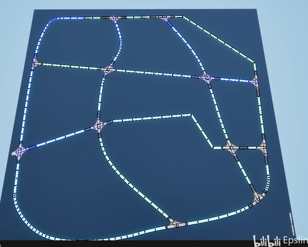
连接连续Segments获得的Debug效果
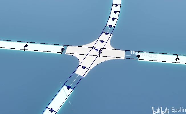
Segments被切断细节
上面这两张图使用DrawSolidBox绘制了连续Segments填充的分段,可以看到在连接处由于被交汇口切断导致道路DebugBox没有连接到路口,我们下面就来解决这个问题。
解决的思路也非常简单,既然我们在生成交汇口的时候剔除了Segment,那么完整生成只需要提取路口的坐标,作为新的分段信息填充回去即可,我们又可以拆成三部分执行:
根据道路端点的坐标,使用四叉树、空间对比获得交界点所在的SegmentIndex。
在连续Segments中搜索应当作为哪一个连续分段的附加信息。
整合内容传递给RoadMeshGenerator。
这里特别强调,新增的连续段点末端到路口这段Segment需要作为附加信息由RoadMeshGenerator处理。这样一方面符合我们前面的框架分工,另一方面也避免新Segment信息引入导致Subsystem中生成的分段被打乱(也就是一边循环一边增删元素的大忌)。
四叉树方面,仿照前面的查询函数使用GetElements()即可,这里不再赘述。这里主要讨论对四叉树返回结果的处理。由于最小网格的存在,我们传入的终点可能会返回多段Segments,我们需要从其中挑选出正确的分段信息,为后面寻找连续分段提供支持。
这里我们利用空间信息进行进一步判断,也就是说通过比较四叉树返回的Segment终点到路口的距离值,选择其中最小的,由此获得路口点所在的SegmentA。这部分的代码段如下:
//位于void URoadGeneratorSubsystem::GenerateRoads()中,前后省略
//2.判断十字路口端点位于哪个Segment、将其作为附加信息与连续Segments封装到FConnectionInsertInfo结构体
		//对应ContinuousSegmentsGroup的二维序号和是否为前缀
		TMultiMap SegmentGroupToConnectionToHead;
		USplineComponent* TargetSplinePtr = SingleSpline.Pin().Get();
		for (const FIntersectionSegment& IntersectionSegment : RoadIntersectionConnectionInfo)
		{
			FBox2D BoxOfConnection(ForceInit);
			BoxOfConnection += FVector2D(IntersectionSegment.IntersectionEndPointWS);
			//这个值比较重要,太小可能搜不到相邻节点,太大要筛选的量过多
			BoxOfConnection = BoxOfConnection.ExpandBy(50.0f);
			TArray PotentialConnection;
			SplineQuadTree.GetElements(BoxOfConnection, PotentialConnection);
			//部分路口外部无衔接道路
			if (PotentialConnection.IsEmpty())
			{
				DrawDebugBox(UEditorComponentUtilities::GetEditorContext()->GetWorld(),
				             IntersectionSegment.IntersectionEndPointWS, FVector(10.0f), FColor::Red, true, -1, 0,
				             5.0f);
				continue;
			}
			if (PotentialConnection.Num() != 1)
			{
				uint32 OwnerSegmentIndex = 0;
				float MinDistance = FLT_MAX;
				for (int i=0;iGetDistanceAlongSplineAtLocation(
				IntersectionSegment.IntersectionEndPointWS, ESplineCoordinateSpace::World);
			FTransform ConnectionTransform = TargetSplinePtr->GetTransformAtDistanceAlongSpline(
				DisOfConnectionOnSpline, ESplineCoordinateSpace::World);
			InsertInfo.ConnectionTrans = ConnectionTransform;
			SegmentGroupToConnectionToHead.Emplace(
				InsertInfo.GroupIndex, InsertInfo);
			//不要直接在这里插入(相当于一边遍历一边修改),会破坏上面的算法
}然后到连续Segment数组中遍历确定SegmentA在连续数组中的"插入位置",但我们不进行实际插入,而是将其封装为一个结构体作为附加信息,结构体名为FConnectionInsertInfo,形式如下:
/**
 * 交点插入到连续分段的信息
 */
struct FConnectionInsertInfo
{
	FConnectionInsertInfo(){};
	/**
	 * 插入到二维数组ContinuousSegmentsGroups中一维的哪一个元素,即作为哪个连续SegmentsGroup的头或尾
	 */
	int32 GroupIndex = -1;
	/**
	 * 插入到连续SegmentsGroup的头部(true)或尾部(false),同时决定了插入位置,头部一定在原有元素之前,尾部一定在原有元素之后
	 */
	bool bConnectToGroupHead = true;
	/**
	* 连接点Transform
	*/
	FTransform ConnectionTrans;
};插入部分对应对应上面代码的 FindInsertIndexInExistedContinuousSegments(),主要工作是根据连接点所在的Segment通过ID索引连续分段中查找插入位置,具体内容如下:
FConnectionInsertInfo URoadGeneratorSubsystem::FindInsertIndexInExistedContinuousSegments(
	const TArray>& InContinuousSegmentsGroups, const TArray& InAllSegmentOnSpline,
	const uint32 OwnerSegmentID, const FVector& PointTransWS)
{
	FConnectionInsertInfo Result;
	//利用连续特性,寻找是不是在端点
	if (OwnerSegmentID < InContinuousSegmentsGroups[0][0])
	{
		Result.GroupIndex = 0;
		Result.bConnectToGroupHead = true;
	}
	else if (OwnerSegmentID > InContinuousSegmentsGroups.Last(0).Last(0))
	{
		Result.GroupIndex = InContinuousSegmentsGroups.Num() - 1;
		Result.bConnectToGroupHead = false;
	}
	else
	{
		int32 IndexDistance = INT_MAX;
		uint32 NeighborSegmentIndex = UINT_MAX;
		bool bChoiceHead = true;
		for (int32 i = 1; i < InContinuousSegmentsGroups.Num(); ++i)
		{
			//@TODO:可以使用二分查找优化
			//遍历寻找中间位置
if (InContinuousSegmentsGroups[i - 1].Last() < OwnerSegmentID && OwnerSegmentID 这里使用结构体封装是为了将分段构成延迟到RoadMeshGenerator中。以实际类比就是施工图已经告知了道路的施工路径和连接点,由现场施工按实际情况连接。这种结构更符合我们之前提到的逐层细化的要求,同时也避免了在已经切割好的二维数组中加入新元素对遍历过程的影响(连续分段序号插入新的、不连续的序号后会降低算法效率)。
在下一步就是创建RoadActor、挂载UDynamicMeshComponent和RoadMeshGenerator(Component),将连续分段的Transform信息和接口处信息传递给RoadMeshGenerator。
RoadMeshGenerator的工作就相对简单了,只需要根据传入信息将连接位置分段和连续分段接在一起即可。
void URoadMeshGenerator::SetRoadInfo(const FRoadSegmentsGroup& InRoadWithConnect)
{
	int32 SweepPathLength = InRoadWithConnect.ContinuousSegmentsTrans.Num();
	SweepPathLength += InRoadWithConnect.bHasHeadConnection ? 1 : 0;
	SweepPathLength += InRoadWithConnect.bHasTailConnection ? 1 : 0;
	SweepPointsTrans.Reserve(SweepPathLength);
	if (InRoadWithConnect.bHasHeadConnection)
	{
		SweepPointsTrans.Emplace(InRoadWithConnect.HeadConnectionTrans);
	}
	SweepPointsTrans.Append(InRoadWithConnect.ContinuousSegmentsTrans);
	if (InRoadWithConnect.bHasTailConnection)
	{
		SweepPointsTrans.Emplace(InRoadWithConnect.TailConnectionTrans);
	}
	bIsLocalSpace = false;
}完成路径生成后,还需要对截面进行一些细微调整。在几何体生成中,顶点需要以逆时针顺序排布。我们可以创建一个结构体,通过成员函数根据道路的宽度和截面高度自动生成坐标,为了直接匹配交叉路口的道路高度,这里使用了以底边对齐Y=0,可以避免后续进行额外参数调整。
//道路数据结构体
USTRUCT(BlueprintType)
struct FLaneMeshInfo
{
	GENERATED_BODY()

public:
	FLaneMeshInfo()
	{
		CrossSectionCoord = FLaneMeshInfo::GetRectangle2DCoords(400.0, 20.0);
	}

	FLaneMeshInfo(const float CrossSectionWidth, const float CrossSectionHeight = 30.0f, const float Length = 1000.0f)
	{
		CrossSectionCoord = FLaneMeshInfo::GetRectangle2DCoords(CrossSectionWidth, CrossSectionHeight);
		SampleLength = Length;
	}

	TArray CrossSectionCoord;
	float SampleLength = 500.0;

protected:
	static TArray GetRectangle2DCoords(float Width, float Height, bool Clockwise = true)
	{
		TArray Rectangle2DCoords;
		Rectangle2DCoords.SetNum(4);
			//逆时针顺序
		TArray UnitShape{{0.5, 1}, {-0.5, 1}, {-0.5, 0.0}, {0.5, 0.0}};
		for (int i = 0; i < UnitShape.Num(); ++i)
		{
			Rectangle2DCoords[i] = FVector2D(Width, Height) * UnitShape[i];
		}
		return Rectangle2DCoords;
	}
};现在我们已经完成了道路扫描中的关键参数生成,只需要再将上面的Transform信息由世界空间转为局部空间,传入UGeometryScriptLibrary_MeshPrimitiveFunctions::AppendSweepPolygon()并像前面的一样修正法线即可实现生成。
至此我们已经完成了道路生成的1.0版本,效果如下:
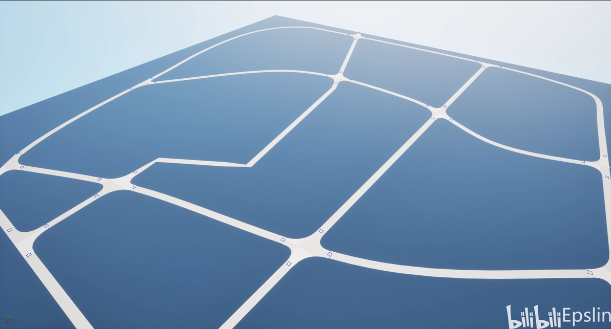
道路生成效果
从上面可以看出,对于使用Curve类型的样条已经符合预期地完成了生成,但对于Linear类型的样条由于在拐角处采样数量不足,造成拐弯处较为生硬;部分道路接口和道路还有一些错位,生成参数还需要进一步优化。这些内容的完善将在本系列后面的文章中再分享。
其他
上面一直有提到但没有展开的一个细节是如何在Editor内挂载Component。众所周知,如果直接调用AddComponent,挂载的Component会在移动Actor时消失、离开关卡后无法保存、在编辑器中无法显示。原因是创建的CreationMethod应该设置为Instance,这里根据UE论坛上的回答给出两种解决方案:
TObjectPtr UEditorComponentUtilities::AddComponentInEditor(AActor* TargetActor,
	TSubclassOf TargetComponentClass)
{
	//有效性检查
	if (nullptr == TargetActor)
	{
		UNotifyUtilities::ShowPopupMsgAtCorner("Null Actor Passed In");
		return nullptr;
	}
	//实现方法1(https://forums.unrealengine.com/t/the-way-i-add-components-to-actor-via-editor-utility-widget/677903/9)
	/*GEditor->BeginTransaction(TEXT("AddComponent"), FText(), nullptr);
	UKismetSystemLibrary::TransactObject(TargetActor);
	USubobjectDataSubsystem* AddCompSubSystem = GEngine->GetEngineSubsystem();
	TArray SubObjectData;
	AddCompSubSystem->GatherSubobjectData(TargetActor, SubObjectData);
	FAddNewSubobjectParams NewCompParam;
	NewCompParam.ParentHandle = SubObjectData[0];
	NewCompParam.NewClass = TargetComponentClass;
	FText FailReason;
	FSubobjectDataHandle AddHandled = AddCompSubSystem->AddNewSubobject(NewCompParam, FailReason);
	if (!AddHandled.IsValid())
	{
		UNotifyUtilities::ShowPopupMsgAtCorner(FailReason.ToString());
		return nullptr;
	}
	const UActorComponent* ConstNewComp = Cast(AddHandled.GetData()->GetObject());
	GEditor->EndTransaction();
	return const_cast(ConstNewComp);*/
	//实现方法2(https://forums.unrealengine.com/t/add-component-to-actor-in-c-the-final-word/646838/9)
	TargetActor->Modify();
	TObjectPtr NewComponent = NewObject(TargetActor, TargetComponentClass);
	NewComponent->OnComponentCreated();
	TObjectPtr NewComponentAsSceneComp = Cast(NewComponent);
	if (nullptr != NewComponentAsSceneComp)
	{
		NewComponentAsSceneComp->AttachToComponent(TargetActor->GetRootComponent(),
												   FAttachmentTransformRules::SnapToTargetIncludingScale);
	}
	NewComponent->RegisterComponent();
	TargetActor->AddInstanceComponent(NewComponent);
	return NewComponent;
}对于蓝图可以使用:
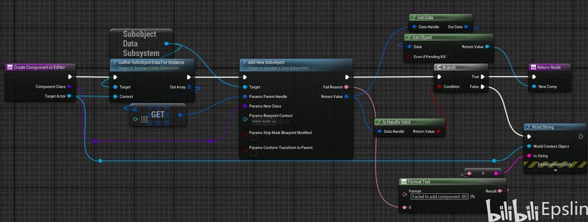
蓝图在Eidtor下挂载Component
关于自动化测试,在文章中有一些纯逻辑算法的函数使用了UnrealTestClass进行测试。UnrealTestClass可以在Rider中组织样例直接进行验证,本文测试的具体内容位于FRoadGeneratorSubsystemTest类中,有两点需要提示:
使用Rider创建的TestClass没有.h文件,如果需要对测试用例和传入、传出进行处理,建议直接创建自由函数,试图无声明创建测试类的成员函数会报错。
对于模板函数建议在自由函数中特化后测试,TestClass中直接声明模板自由函数同样会报错。
以上就是本次分享的全部内容,希望对大家有所帮助!
