目录

旋转式“刮擦全息”代码分享(带遮挡)

最近很火的刮擦全息,其实有两种
一种是左右平移观察的,其中以 Matt Brand 为先驱:
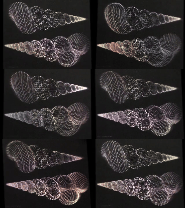
https://zintaglio.com/available.html
此种刮擦全息的划痕形状为双曲线,在 8° 观察角范围内可近似为圆弧*
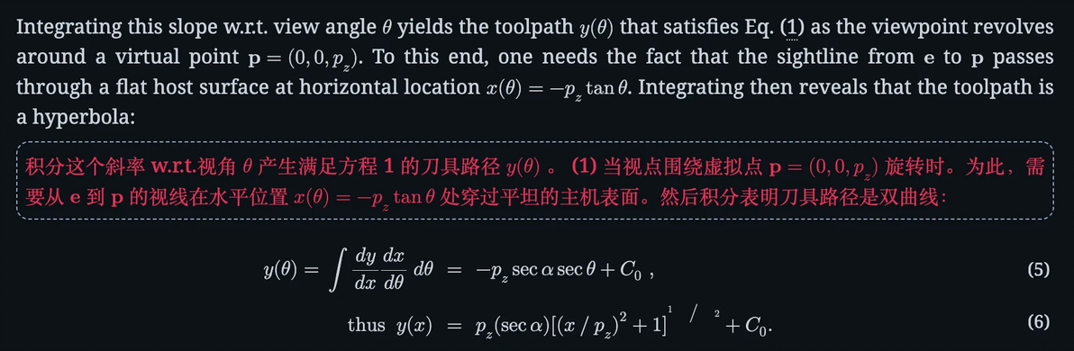
Brand, M. (2011). Specular holography. Applied Optics, 50(25), 5042-5046.
众多开源程序亦采用圆弧简化计算
有一个付费软件 Holocraft 用到了准确的双曲线形状,卖 29.9 刀,最近大家站内见到的左右平移式“刮擦全息”应该都是它的作品。
这个软件确实做得很好,我就不做重复工作了。(可以找@刮擦全息艺术家(坏坏) 加拼团群)
但其实还有一种刮擦全息
就是星球大战唱片上的这种,旋转式观察的
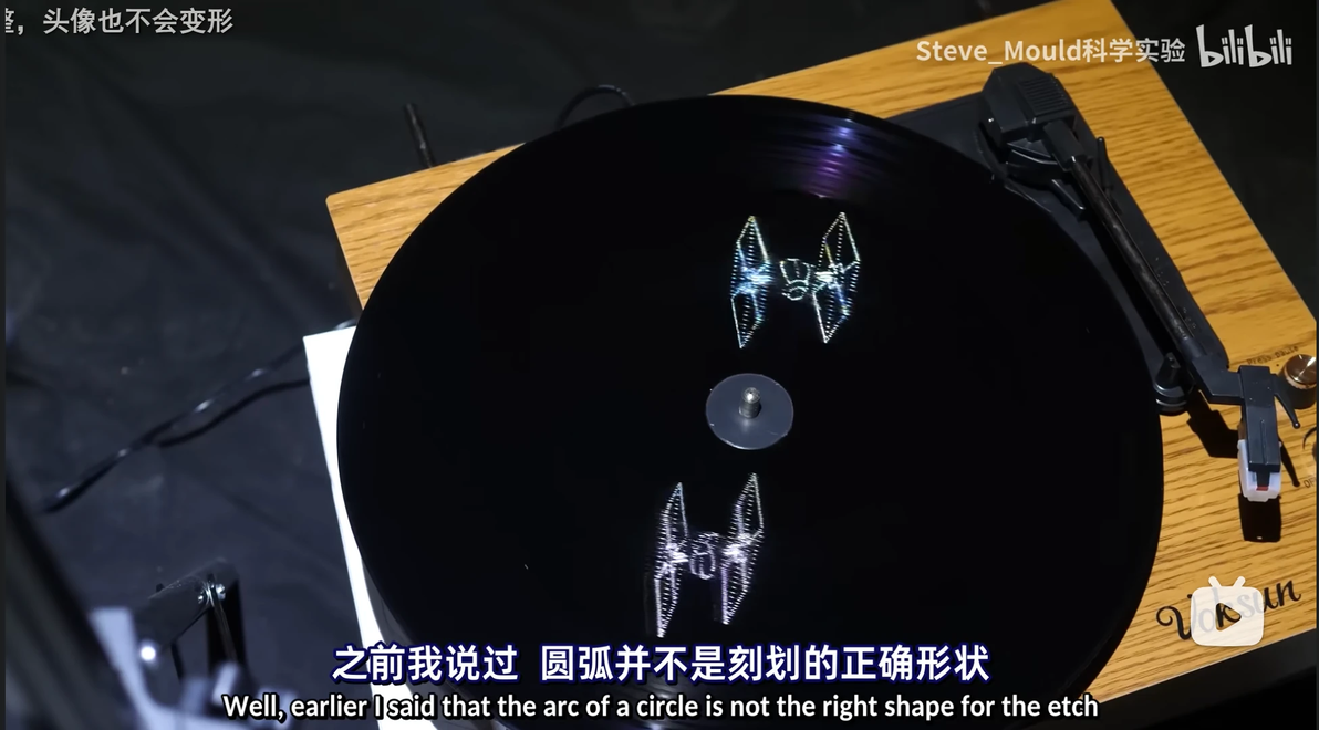
是的,SteveMould也做过一期视频
这种的原理相对简单,但奇怪的是没有开源程序做这个,何不自己来呢?
很简单,就是对于物体表面的采样点,其在平面
上的划痕曲线就是
以 为圆心,半径为
的圆
为人眼视线与z轴的夹角,也就是天顶角
然后对射线进行遮挡判断,被遮挡的方位角没有划痕...
......
多说无益,放代码吧,99%由 o1-mini 生成
输入STL或OBJ模型文件,输出DXF划痕文件
代码块
Python
自动换行
复制代码
"""
@author: 贰鼠 & o1-mini
@date: 2024-12-11
@version: 3.0.1
@description: 刮擦全息划痕生成
"""
import trimesh
import numpy as np
import ezdxf
from math import radians, degrees, tan, sin, cos, ceil
import argparse
from collections import defaultdict
from concurrent.futures import ProcessPoolExecutor, as_completed
from tqdm import tqdm
import sys
import pyvista as pv

def load_and_process_model(file_path=None, target_size=0.1):
    """
    加载STL或OBJ模型,如果未提供文件路径,则使用默认的正方体。
    将模型的几何中心移动到原点,并缩放到指定大小(默认10厘米)。
    """
    try:
        if file_path:
            mesh = trimesh.load(file_path)
        else:
            # 创建一个默认的正方体,边长为10厘米
            mesh = trimesh.creation.box(extents=[0.1, 0.1, 0.1])
            print("使用默认的正方体进行测试。")

        # 确保模型是三角网格
        if isinstance(mesh, trimesh.Scene):
            mesh = trimesh.util.concatenate(mesh.dump())
        elif isinstance(mesh, trimesh.Trimesh):
            pass
        else:
            raise ValueError("加载的模型类型不受支持。请提供有效的STL或OBJ文件。")

        # 计算几何中心并移动到原点
        centroid = mesh.centroid
        mesh.apply_translation(-centroid)

        # 计算缩放因子以将模型最大尺寸缩放到目标大小
        bounding_box = mesh.bounds
        size = bounding_box[1] - bounding_box[0]
        max_dim = np.max(size)
        scale_factor = target_size / max_dim
        mesh.apply_scale(scale_factor)

        print(f"模型已移动到原点并缩放到 {target_size*100} cm。")
        return mesh
    except Exception as e:
        print(f"加载和处理模型时出错: {e}")
        sys.exit(1)

def extract_edges(mesh, normal_threshold_deg=10.0):
    """
    提取模型的唯一边缘,并过滤掉法线夹角小于阈值的边缘。

    参数:
    - mesh: trimesh.Trimesh 对象
    - normal_threshold_deg: 法线夹角阈值,单位为度

    返回:
    - edge_vertices: 过滤后的边缘顶点数组
    """
    try:
        edges = mesh.edges_unique
        # 使用 face_adjacency_edges 和 face_adjacency 来构建 edges_unique_faces
        # 创建一个字典,键为排序后的边,值为相邻的面索引
        edge_to_faces = defaultdict(list)
        for i, edge in enumerate(mesh.face_adjacency_edges):
            # 将边排序以确保一致性
            sorted_edge = tuple(sorted(edge))
            # 获取相邻的两个面
            face_pair = mesh.face_adjacency[i]
            edge_to_faces[sorted_edge].extend(face_pair)

        # 构建 edges_unique_faces
        edges_unique_faces = []
        for edge in edges:
            sorted_edge = tuple(sorted(edge))
            faces = edge_to_faces.get(sorted_edge, [])
            if len(faces) == 0:
                # 无相邻面,可能是孤立边
                edges_unique_faces.append([-1, -1])
            elif len(faces) == 1:
                # 边界边,仅有一个相邻面
                edges_unique_faces.append([faces[0], -1])
            else:
                # 正常边,两个相邻面
                edges_unique_faces.append([faces[0], faces[1]])

        # 计算每条边的法线夹角
        face_normals = mesh.face_normals
        angles = []
        for face_pair in edges_unique_faces:
            if face_pair[1] == -1:
                # 边界边(只有一个相邻面),通常保留
                angles.append(180.0)
            else:
                normal1 = face_normals[face_pair[0]]
                normal2 = face_normals[face_pair[1]]
                # 计算法线夹角
                dot_product = np.clip(np.dot(normal1, normal2), -1.0, 1.0)
                angle = degrees(np.arccos(dot_product))
                angles.append(angle)

        angles = np.array(angles)
        # 保留法线夹角大于或等于阈值的边缘
        sharp_edge_mask = angles >= normal_threshold_deg
        filtered_edges = edges[sharp_edge_mask]

        # 获取对应的顶点
        vertices = mesh.vertices
        edge_vertices = vertices[filtered_edges]
        print(f"提取到 {len(edge_vertices)} 条唯一尖锐边缘(法线夹角 >= {normal_threshold_deg}°)。")
        return edge_vertices
    except Exception as e:
        print(f"提取边缘时出错: {e}")
        sys.exit(1)

def sample_points_on_edges(edge_vertices, d=0.002):
    """
    在每条边缘上按照标准距离d均匀采样点,并去除重复的端点。

    参数:
    - edge_vertices: 边缘顶点数组
    - d: 点之间的标准距离(米)

    返回:
    - sampled_points: 去重后的采样点数组
    """
    try:
        sampled_points = []
        for edge in edge_vertices:
            start, end = edge
            # 计算边的长度
            edge_vector = end - start
            length = np.linalg.norm(edge_vector)
            if length == 0:
                # 零长度边,跳过
                continue
            # 计算需要采样的点数
            num_segments = max(1, ceil(length / d))
            for i in range(num_segments + 1):
                t = i / num_segments
                point = (1 - t) * start + t * end
                sampled_points.append(point)
        sampled_points = np.array(sampled_points)
        sampled_points = np.unique(sampled_points, axis=0) # 去除重复的采样点
        print(f"在边缘上采样了 {len(sampled_points)} 个唯一的点。")
        return sampled_points
    except Exception as e:
        print(f"采样点时出错: {e}")
        sys.exit(1)

def generate_ray_directions(theta_deg=45, num_rays=360, epsilon_azimuth=0.1):
    """
    生成一圈射线方向,射线与z轴的夹角为theta_deg(天顶角)。
    为避免过于规整的模型导致射线重合,添加一个微小的偏移量到方位角。

    参数:
    - theta_deg: 射线与z轴的夹角,单位为度
    - num_rays: 射线的数量
    - epsilon_azimuth: 方位角的微小偏移量,单位为度(也用于theta天顶角)

    返回:
    - directions: 射线方向的数组
    - azimuths: 方位角数组(已偏移)
    """
    try:
        theta = radians(theta_deg + epsilon_azimuth) # 借用方位角的微小偏移量
        azimuths = np.linspace(0, 360, num_rays, endpoint=False) # 可以修改这里的角度实现部分圆弧,比如[-30,30]
        # 添加微小偏移量以避免射线重合
        azimuths = (azimuths + epsilon_azimuth) % 360
        directions = []
        for az in azimuths:
            az_rad = radians(az)
            dx = sin(theta) * cos(az_rad)
            dy = sin(theta) * sin(az_rad)
            dz = cos(theta)
            directions.append([dx, dy, dz])
        return np.array(directions), azimuths
    except Exception as e:
        print(f"生成射线方向时出错: {e}")
        sys.exit(1)

def collect_visible_intervals(visible_angles, angle_tolerance=1.0):
    """
    将可见的方位角整理为连续的区间。
    """
    if len(visible_angles) == 0:
        return []

    sorted_angles = np.sort(visible_angles)
    intervals = []
    start = sorted_angles[0]
    prev = sorted_angles[0]

    for angle in sorted_angles[1:]:
        if angle - prev > angle_tolerance:
            intervals.append((start, prev))
            start = angle
        prev = angle
    intervals.append((start, prev))

    # 检查是否需要合并第一个和最后一个区间(圆周连续)
    if len(intervals) > 1:
        first_start, first_end = intervals[0]
        last_start, last_end = intervals[-1]
        if first_start <= angle_tolerance and (360 - last_end) <= angle_tolerance:
            intervals[0] = (last_start, first_end)
            intervals.pop()

    return intervals

def write_dxf(circles, dxf_file='output.dxf'):
    """
    将圆或圆弧写入DXF文件。
    """
    try:
        doc = ezdxf.new(dxfversion='R2010')
        msp = doc.modelspace()

        for circle in circles:
            center = circle['center']
            radius = circle['radius']
            start_angle = circle.get('start_angle')
            end_angle = circle.get('end_angle')

            if start_angle is None and end_angle is None:
                # 完整的圆
                msp.add_circle(center, radius)
            else:
                # 圆弧
                msp.add_arc(center, radius, start_angle, end_angle)

        doc.saveas(dxf_file)
        print(f"DXF文件已保存为 {dxf_file}。")
    except Exception as e:
        print(f"写入DXF文件时出错: {e}")
        sys.exit(1)

def process_sampled_point(args):
    """
    处理单个采样点,执行可见性分析并返回生成的圆或圆弧。

    参数:
    - args: 包含所有必要参数的元组

    返回:
    - circles: 生成的圆或圆弧列表
    """
    point, ray_directions, azimuths, ray_intersector, theta_deg, l, offset_distance, angle_tolerance = args
    try:
        origin = point.copy()
        # 为避免自我相交,沿射线方向偏移一定距离
        origins = origin + ray_directions * offset_distance

        # 发射射线并检查交点
        locations, index_ray, _ = ray_intersector.intersects_location(
            ray_origins=origins,
            ray_directions=ray_directions,
            multiple_hits=False
        )

        # 初始化所有射线为可见
        visible = np.ones(len(ray_directions), dtype=bool)
        # 被阻挡的射线不可见
        visible[index_ray] = False
        visible_angles = azimuths[visible]

        # 收集可见的方位角区间
        intervals = collect_visible_intervals(visible_angles, angle_tolerance=angle_tolerance)

        # 计算圆的半径
        x, y, z = point
        radius = z * tan(radians(theta_deg)) + l

        circles = []

        if not intervals:
            # 如果没有可见区间,不绘制任何圆
            return circles

        for interval in intervals:
            if len(interval) == 2:
                start_angle, end_angle = interval
                # 检查是否覆盖整个360度
                if end_angle - start_angle >= 360 - 1.0:
                    circles.append({
                        'center': (x, y, 0),
                        'radius': radius,
                        'start_angle': None,
                        'end_angle': None
                    })
                else:
                    # **关键修正:调整角度以消除180度偏差**
                    adjusted_start = (start_angle + 180) % 360
                    adjusted_end = (end_angle + 180) % 360
                    circles.append({
                        'center': (x, y, 0),
                        'radius': radius,
                        'start_angle': adjusted_start,
                        'end_angle': adjusted_end
                    })
            else:
                # 完整的圆
                circles.append({
                    'center': (x, y, 0),
                    'radius': radius,
                    'start_angle': None,
                    'end_angle': None
                })

        return circles
    except Exception as e:
        print(f"处理采样点时出错: {e}")
        return []

def visualize_results(mesh, edges, sampled_points, theta_deg):
    """
    使用 PyVista 可视化模型、边缘和采样点。
    增加一个滑块控制方位角,并添加按钮切换投影模式(透视/正交)。
    设置固定视角,模拟从天顶角 θ 观察。
    """
    try:
        pv_mesh = pv.wrap(mesh)

        # 创建边缘线条
        edges_flat = edges.reshape(-1, 3)
        edge_lines = []
        num_edges = len(edges_flat) // 2
        for i in range(num_edges):
            edge_lines.append([2, i*2, i*2 + 1])
        edge_polydata = pv.PolyData(edges_flat)
        edge_polydata.lines = np.hstack(edge_lines)

        # 创建采样点
        point_cloud = pv.PolyData(sampled_points)

        # 创建绘图窗口
        plotter = pv.Plotter()
        plotter.add_mesh(pv_mesh, color='lightgray', show_edges=True, opacity=0.5, label='Model')
        plotter.add_mesh(edge_polydata, color='red', line_width=2, label='Edges')
        plotter.add_mesh(point_cloud, color='blue', point_size=5, render_points_as_spheres=True, label='Sampled Points')

        # 设置固定视角
        theta_rad = radians(theta_deg)
        r = np.max(mesh.bounds[1] - mesh.bounds[0]) * 3  # 距离设置为模型最大尺寸的3倍
        initial_azimuth = 0  # 初始方位角为0度
        camera_position = (r * sin(theta_rad) * cos(radians(initial_azimuth)),
                           r * sin(theta_rad) * sin(radians(initial_azimuth)),
                           r * cos(theta_rad))
        plotter.camera_position = [
            camera_position,  # Camera location
            (0, 0, 0),        # Focal point
            (0, 0, 1)         # View up direction
        ]

        # 初始化投影模式为透视
        plotter.disable_parallel_projection()

        # 定义滑块回调函数,修改为接受可变数量的参数
        def update_camera(*args, **kwargs):
            """
            更新相机位置的回调函数。

            接受可变数量的参数,以兼容PyVista的回调机制。
            """
            if len(args) > 0:
                azimuth = args[0]
            else:
                azimuth = 0  # 默认值,避免错误
            az_rad = radians(azimuth)
            new_x = r * sin(theta_rad) * cos(az_rad)
            new_y = r * sin(theta_rad) * sin(az_rad)
            new_z = r * cos(theta_rad)
            plotter.camera_position = [
                (new_x, new_y, new_z),  # 新的摄像机位置
                (0, 0, 0),               # 焦点不变
                (0, 0, 1)                # 上方向不变
            ]
            plotter.render()

        # 定义按钮回调函数,添加一个参数以匹配PyVista的回调要求
        projection_mode = {'parallel': False}  # 使用字典以便在内部修改

        def toggle_projection(*args, **kwargs):
            """
            切换投影模式的回调函数。

            接受可变数量的参数,以兼容PyVista的回调机制。
            """
            if projection_mode['parallel']:
                plotter.disable_parallel_projection()
                projection_mode['parallel'] = False
                print("已切换到透视投影模式。")
            else:
                plotter.enable_parallel_projection()
                projection_mode['parallel'] = True
                print("已切换到正交投影模式。")
            plotter.render()

        # 添加滑块控件
        plotter.add_slider_widget(
            callback=update_camera,
            rng=[0, 360],
            value=initial_azimuth,
            title="azimuth(°)",
            pointa=(.025, .1),
            pointb=(.225, .1),
            style='modern'
        )

        # 添加按钮控件
        plotter.add_checkbox_button_widget(
            callback=toggle_projection,
            # size=20,
            # position=(0.85, 0.1),
        )
        plotter.add_text("switch to parallel projection", position='lower_left', font_size=10)

        plotter.add_legend()
        plotter.show()
    except Exception as e:
        print(f"可视化时出错: {e}")

def main():
    parser = argparse.ArgumentParser(description="处理STL或OBJ模型并生成DXF文件。")
    parser.add_argument('--file', type=str, help="输入的STL或OBJ文件路径。")
    parser.add_argument('--theta', type=float, default=45.0, help="射线与z轴的夹角(天顶角,默认45°)。")
    parser.add_argument('--output', type=str, default='output.dxf', help="输出的DXF文件名。")
    parser.add_argument('--d', type=float, default=0.002, help="点之间的标准距离(米),默认0.002米。")
    parser.add_argument('--full_circles', action='store_true', help="启用此标志以生成完整的圆而不进行可见性分析。")
    parser.add_argument('--normal_threshold', type=float, default=10.0, help="法线夹角阈值(度),小于该阈值的边缘将被忽略。默认10°。")
    parser.add_argument('--epsilon_azimuth', type=float, default=0.1, help="方位角的微小偏移量(度),默认0.1°。用于避免射线重合。")
    parser.add_argument('--offset', type=float, default=0.15, help="偏移量(米),控制最终圆弧的大致半径,默认0.15米。")
    parser.add_argument('--visualize', action='store_true', help="启用此标志以进行可视化验证。")
    args = parser.parse_args()

    # 加载并处理模型
    mesh = load_and_process_model(file_path=args.file, target_size=0.1)  # 0.1米即10厘米

    # 提取尖锐边缘
    edges = extract_edges(mesh, normal_threshold_deg=args.normal_threshold)

    # 采样点
    sampled_points = sample_points_on_edges(edges, d=args.d)

    if args.visualize:
        # 可视化结果
        visualize_results(mesh, edges, sampled_points, args.theta)

        # 提示用户是否继续
        while True:
            user_input = input("是否继续处理?请输入 [y/n]: ").strip().lower()
            if user_input == 'y':
                break
            elif user_input == 'n':
                print("程序已退出。")
                sys.exit(0)
            else:
                print("输入无效。请输入 'y' 或 'n'。")

    if args.full_circles:
        print("启用完整圆模式,不进行可见性分析。")
        # 仅计算每个点的圆并写入DXF
        circles = []
        l = args.offset  # 使用输入的偏移量
        theta_rad = radians(args.theta)
        try:
            for idx, point in enumerate(tqdm(sampled_points, desc="生成完整圆", unit="点")):
                x, y, z = point
                radius = z * tan(theta_rad) + l
                circles.append({
                    'center': (x, y, 0),
                    'radius': radius,
                    'start_angle': None,
                    'end_angle': None
                })
            # 写入DXF文件
            write_dxf(circles, dxf_file=args.output)
        except Exception as e:
            print(f"生成完整圆时出错: {e}")
            sys.exit(1)
    else:
        print("启用可见性分析模式。")
        # 生成射线方向,添加微小偏移量
        ray_directions, azimuths = generate_ray_directions(theta_deg=args.theta, num_rays=360, epsilon_azimuth=args.epsilon_azimuth)

        # 初始化射线交叉器
        try:
            ray_intersector = trimesh.ray.ray_pyembree.RayMeshIntersector(mesh)
            print("使用PyEmbree进行加速的射线交叉。")
        except ImportError:
            ray_intersector = trimesh.ray.ray_triangle.RayMeshIntersector(mesh)
            print("使用Trimesh内置的射线交叉。")
        except Exception as e:
            print(f"初始化射线交叉器时出错: {e}")
            sys.exit(1)

        # 收集需要绘制的圆或圆弧
        circles = []
        l = args.offset  # 使用输入的偏移量
        offset_distance = 1e-5  # 偏移量避免自我相交
        angle_tolerance = 1.0  # 可见性分析的角度容差

        # 准备并行处理的参数
        process_args = [
            (point, ray_directions, azimuths, ray_intersector, args.theta, l, offset_distance, angle_tolerance)
            for point in sampled_points
        ]

        try:
            with ProcessPoolExecutor() as executor:
                futures = {executor.submit(process_sampled_point, arg): idx for idx, arg in enumerate(process_args)}
                for future in tqdm(as_completed(futures), total=len(futures), desc="进行可见性分析", unit="点"):
                    result = future.result()
                    if result:
                        circles.extend(result)
        except Exception as e:
            print(f"并行处理时出错: {e}")
            sys.exit(1)

        print(f"总共生成了 {len(circles)} 条圆或圆弧。")

        # 写入DXF文件
        write_dxf(circles, dxf_file=args.output)

    # if args.visualize and not args.full_circles:
    #     # 可视化结果(仅模型、边缘和采样点)
    #     visualize_results(mesh, edges, sampled_points, args.theta)

if __name__ == "__main__":
    main()
复制成功
使用方法:
① 复制代码保存为 holo.py
② 在终端装好依赖库
代码块
Shell
自动换行
复制代码
pip install trimesh numpy ezdxf tqdm pyvista复制成功
③ 在终端传参数运行程序(以下是示例)
代码块
Shell
自动换行
复制代码
python holo.py --file path/to/model.stl --output path/to/output.dxf --normal_threshold 30.0 --d 0.01 --visualize复制成功
传入参数解释:
代码块
Shell
自动换行
复制代码
$ python holo.py --help
usage: main3_1.py [-h] [--file FILE] [--theta THETA] [--output OUTPUT] [--d D] [--full_circles] [--normal_threshold NORMAL_THRESHOLD] [--epsilon_azimuth EPSILON_AZIMUTH] [--offset OFFSET] [--visualize]

处理STL或OBJ模型并生成DXF文件。

options:
  -h, --help            show this help message and exit
  --file                输入的STL或OBJ文件路径。
  --theta               射线与z轴的夹角(天顶角,默认45°)。
  --output              输出的DXF文件名。
  --d                   采样点之间的标准距离(米),默认0.002米。设为1即为只取端点。
  --full_circles        启用此标志以生成完整的圆而不进行可见性分析。
  --normal_threshold    法线夹角阈值(度),小于该阈值的边缘将被忽略。默认10°。
  --epsilon_azimuth     方位角的微小偏移量(度),默认0.1°。用于避免射线重合。
  --offset              偏移量(米),控制最终圆弧的大致半径,默认0.15米。
  --visualize           启用此标志以进行可视化验证。
复制成功
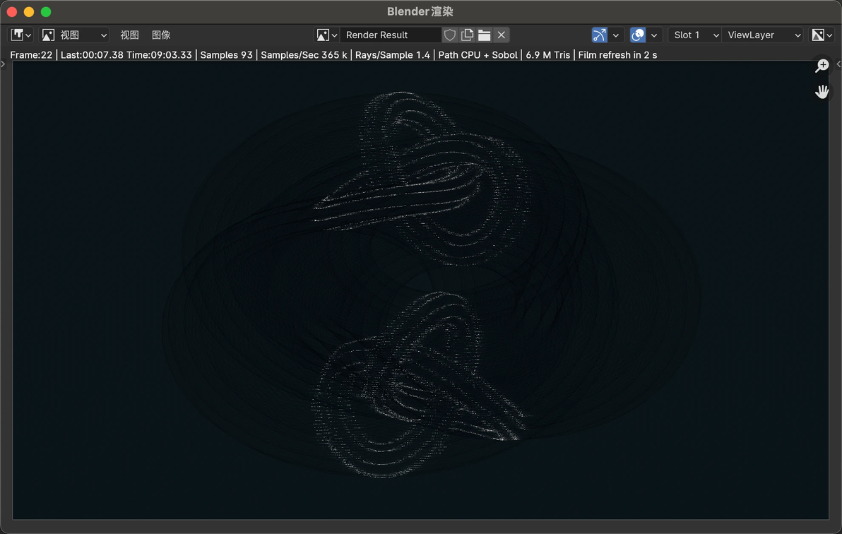
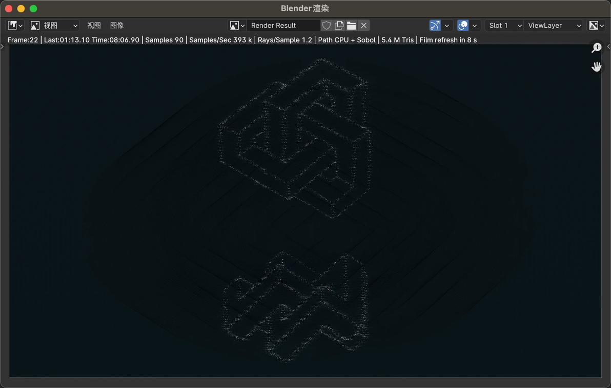
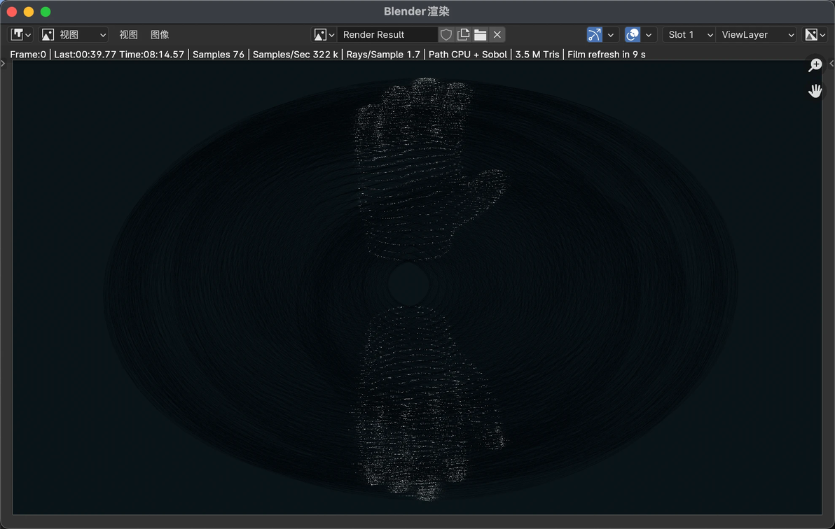
以下是生成的一些成果(都是渲染图,实物还在找人打)
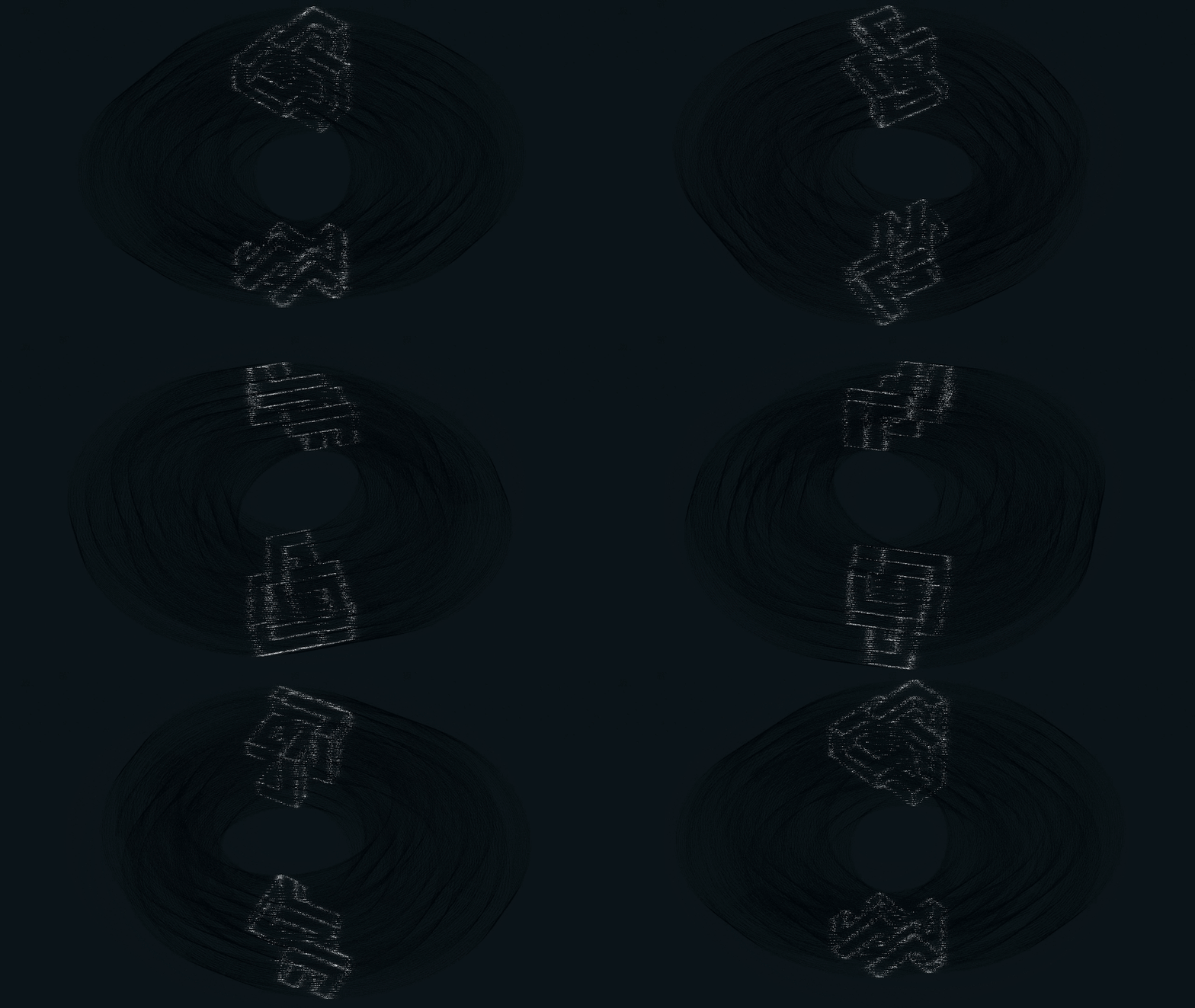
期待有人能改进代码,改进方向有以下几点:
- 从正交投影改为透视投影
- 视角在旋转的同时,为模型也加上运动
- 其它我暂时没能想到的
欢迎大家做出实物了艾特我 ;)
我自己打的到货了估计也会发视频
cv40086937
分享至
投诉或建议
